Register#
Definition#
Info:
A group of flip-flops with gates that determine how the information is transferred into the register.
For example, here is a basic 4-bit register:
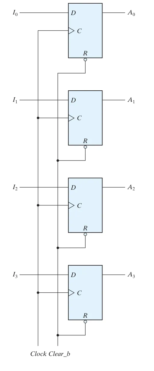
To be useful, a register should keep its data until directed by a load control signal to read in new data.
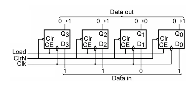
This is a 4-bit register built using DFFs with enable(CE).
Data transfer#
Parallel transfer#
All the bits of a register are transferred at the same time.
Serial transfer#
Information is transferred one bit at a time. Shifts the bits out of a source register into a destination register.
Parallel transfer#
4-bit register with load control#
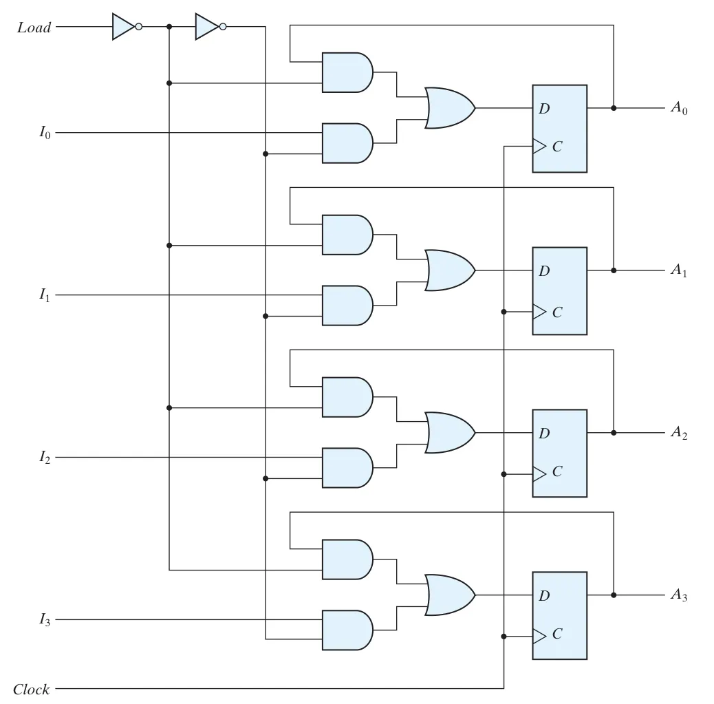
Since a DFF don’t have a “no change” state, so we need to use load to decide the next state is Input or last state.
Transfer selector#
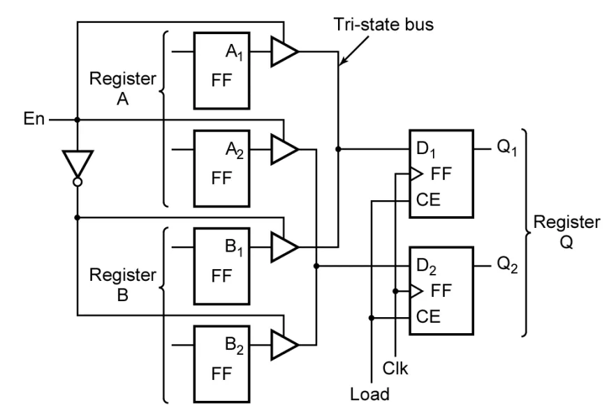 Take a look at the above circuit, describe what can be done between registers A, B, Q?
Answer:
Take a look at the above circuit, describe what can be done between registers A, B, Q?
Answer:
We can observe that there are two control inputs: En, Load.
-
En : Decides which data to use, here is regester A or regerster B.
-
Load : whether to load the data.
So its easy to see that Q will choose a register between A and B and read their data.
Parallel adder#
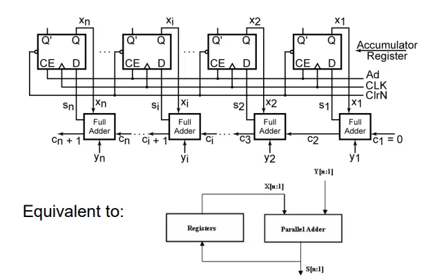
This is a adder that will do
X<=X+Y.
Serial transfer#
Shift register#
It is a kind of register that can shift its data in one or both directions.
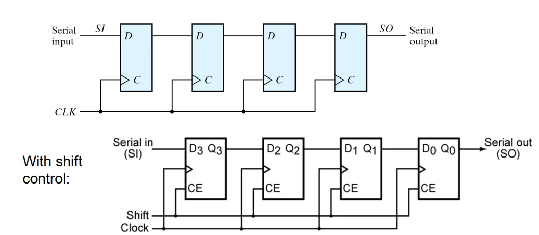
This is a 4-bit serial-in, serial-out right shift registers.
Serial transfer#
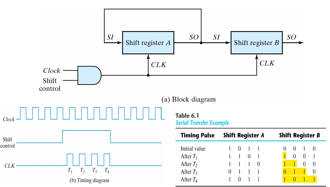
This is a serial transfer from reg A to reg B.
Serial adder#
- Adds two numbers serially with a single FA and a carry FF starting at the least significant bit. (Recall that in parallel adder, n-bits use n FAs)
- It takes n clock cycles to add two n-bit numbers.
- It’s smaller but slower than a parallel adder.
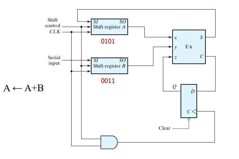 Lets look at the above example and analyze it.
| 0101 | X | 0011 | X | 0 | X | X |
| 0101 | 1 | 0011 | 1 | 0 | 0 | 1 |
| 0010 | 0 | 1001 | 1 | 1 | 0 | 1 |
| 0001 | 1 | 1100 | 0 | 1 | 0 | 1 |
| 0000 | 0 | 0110 | 0 | 1 | 1 | 0 |
| 1000 | X | 0011 | X | 0 | X | X |
Types of shift registers#
- Undirectional shift registers
- Bidirectional shift registers
Universal shift registers#
- Has both direction shifts and parallel load/access capabilities.
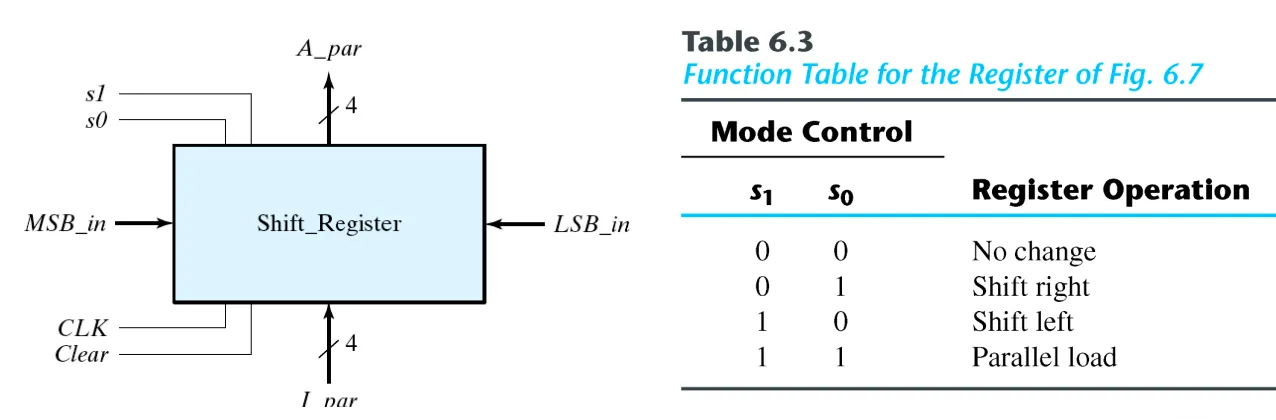 Here is how this univeral shift register is made.
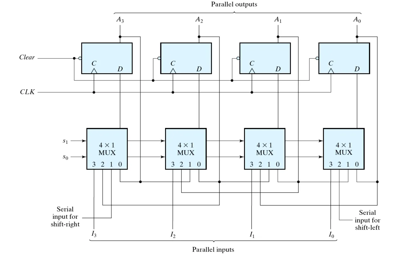 equals to Serial input for shift-right.
equals to Serial input for shift-left.
equals to Serial input for shift-right.
equals to Serial input for shift-left.
Verilog Implementation#
Here is a example of 4-bit Left Shift Register with Reset:
module srg_4_r_v (CLK, RESET, SI, Q, SO);
    input CLK, RESET, SI;
    output [3:0] Q;
    output SO;
    reg [3:0] Q;

    assign SO = Q[3];

    always@ (posedge CLK or posedge RESET)
    begin
        if (RESET)
            Q <= 4'b0000;
        else
            Q <= {Q[2:0], SI};
    end
endmodule