Counter#
Counters are special sequential circuits that sequence though some prescribed set of outputs.
For example:
- Binary counter: 000->001->010->…->111->000
- BCD counter: 0000->0001->0010->…->->1001->0000
Counters are classified into two board categories according to the way they are clocked.
Ripple Counter#
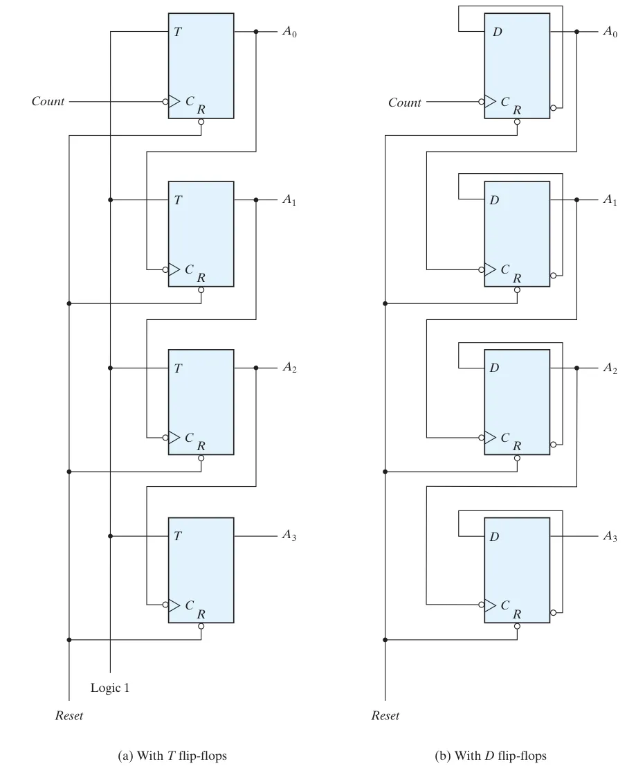
The first flip-flop is clocked by the external clock pulse and then each successive flip-flop is clocked by the output of the preceding flip-flop.
Hence, this is an asynchronous sequential circuit.
Binary Ripple Counter#
This is a ripple counter because when the count is changed, the -th bit only changes after the -th bit has changed. ( The flip-flops’ outputs don’t change synchronously together. )
There are two ways to implement:
BCD Counter (Asynchronous)#
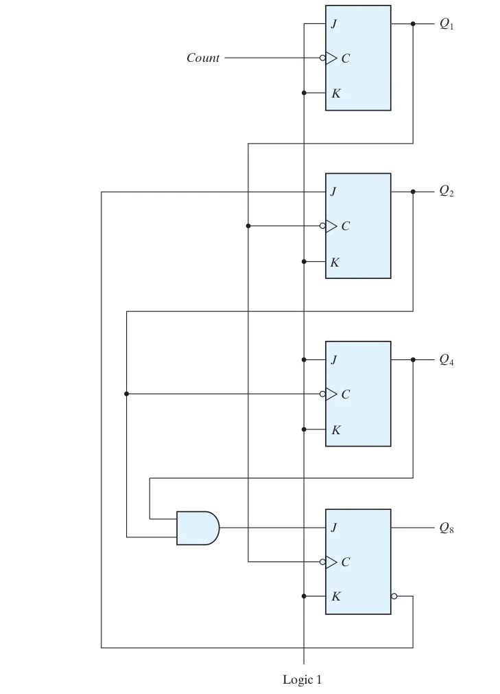
This is a asynchronous implementation of BCD counters.
By the characteristic equation of JKFF, we have:
Since for a BCD counter, it should count to at most 9, so we retrict it by .
Notice that all the clks here are negative-edge triggered.
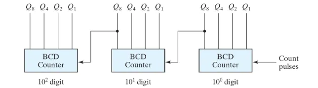
By using mutiple BCD counter, we can have a asynchronous multi-digit BCD counter.
Synchronous Counter#
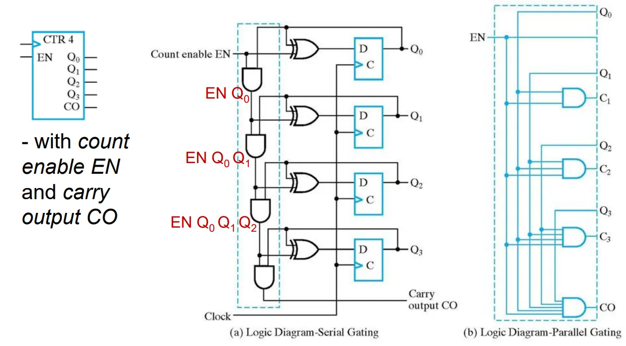
All flip-flops are clocked simultaneously by the external clock pulse.
Synchronous Binary Counter#
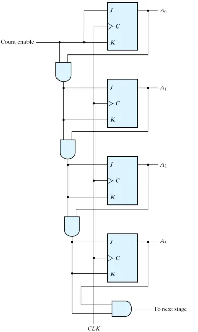
is toggled every clock cycle. needs to be toggled in the next state if to are all one in the present state.
By DFF#
We can get the characteristic function of each DFF:
By JKFF#
We can get the characteristic function of each JKFF:
Exercise#
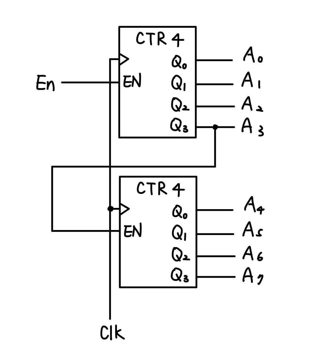
Construct an 8-bit synchronous binary counter using two instances of the 4-bit binary counter. Answer:
Up-Down Binary Counter#
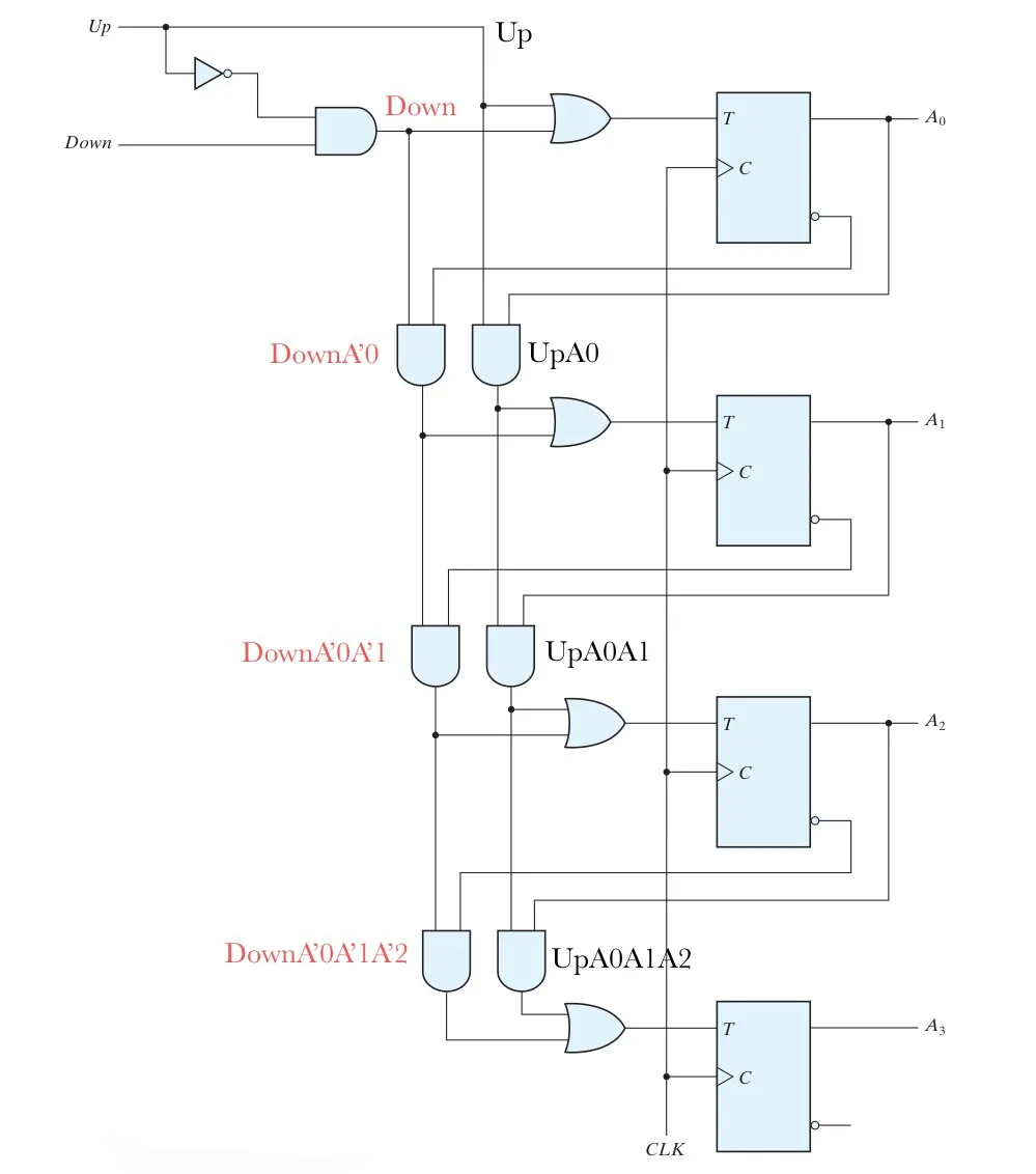
The above counters we had made are up counter.
For a down counter :
- Counts downward.
- Least Significant Bit is complemented each time.
- Other bit position is complemented if all lower bits are 0 (e.g. 1000 -> 0111)
Binary Counter with Parallel Load#
It is desirable if we may load an initial count and/or clear a counter.
This is an example of 4-bit binary counter with parallel load and active-low clear.
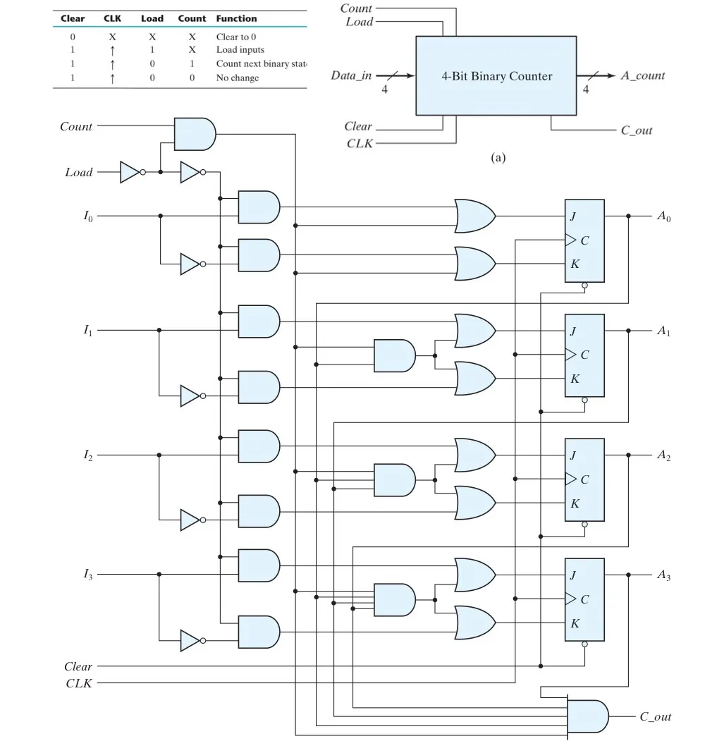 Let’s analyze the circuit.
Also, we have that , so we can say that under any cases.
Now, if , then we get the same as the binary counter above, so now it work as a counter.
Now, if , then are in opposite signal, so it just work as a flip-flop that is updating its data.
BCD Counter (Synchronous)#
Here, we can build BCD counter in an differnt way — By using a 4-bit binary counter.
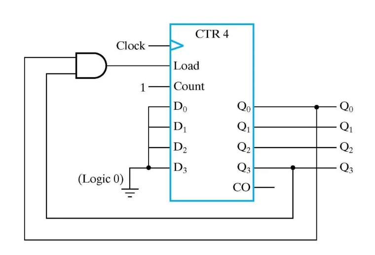
The same as the BCD counter above, we need to control the upper bound of the counter to be 9, so as long as you count to 9, you need to load a 0 so it can restart.
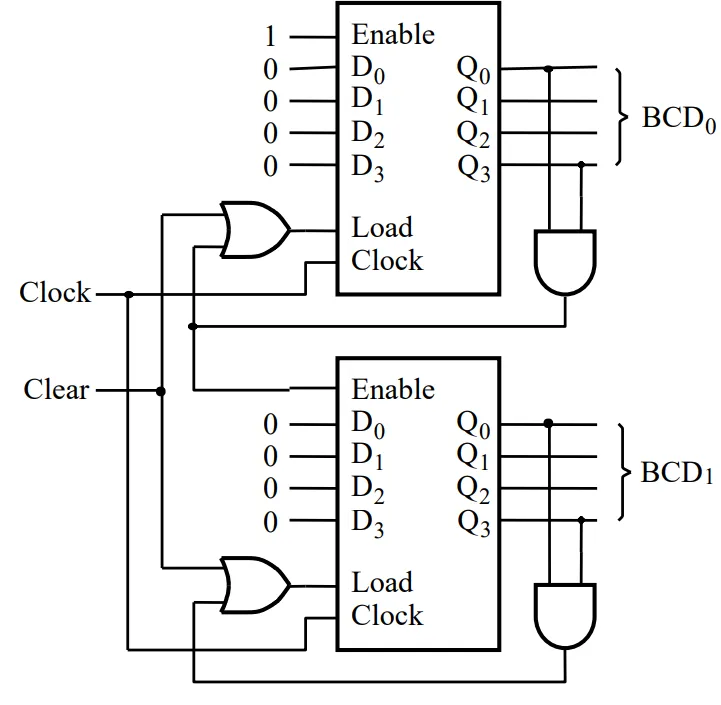
By using mutiple BCD counter, we can have a synchronous multi-digit BCD counter.
Arbitrary Sequence Counter#
Given a counting sequence, implement it with sequential circuit.
Example 01#
Success:
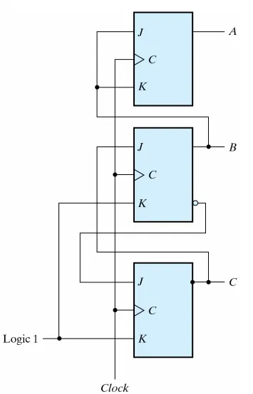
Construct a counter that counts in the sequence 000, 001, 010, 100, 101, 110 repeatedly.
First, we can draw the state table and state diagram:
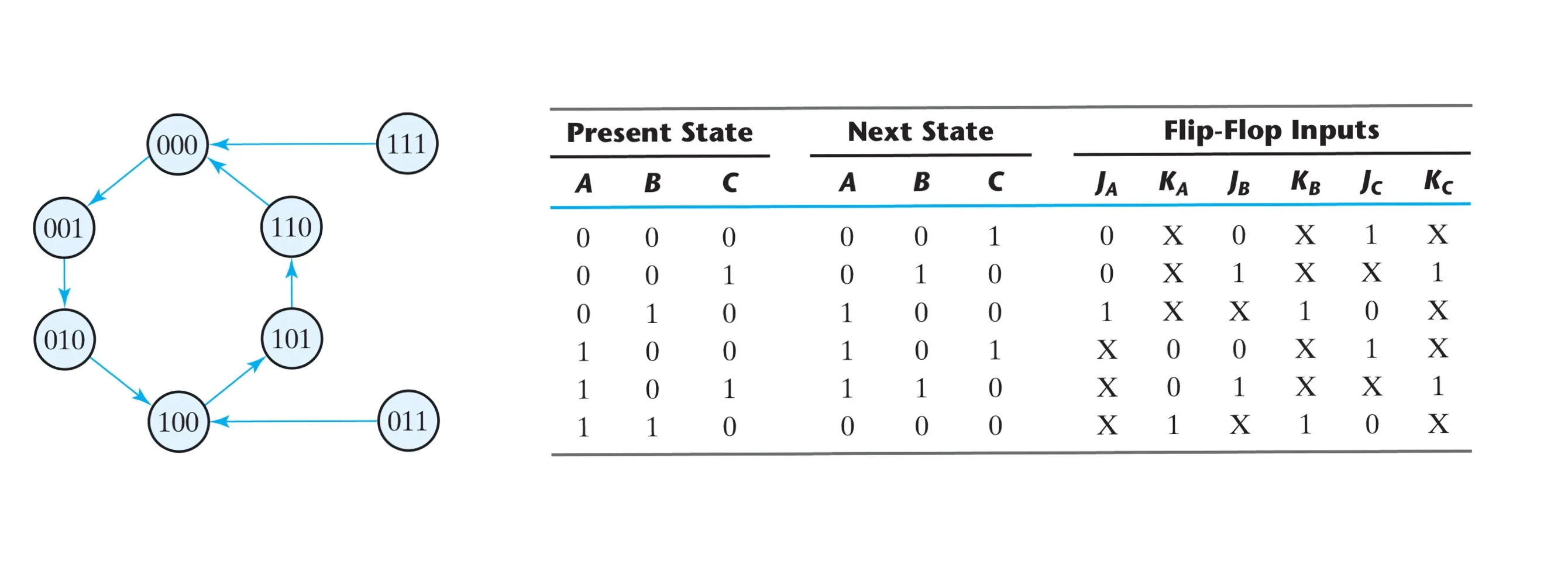 Here, we regard the two unused state 111 and 011 as don’t care conditions, and we can simplify the eqation by using K-map.
K-map:
Here, we regard the two unused state 111 and 011 as don’t care conditions, and we can simplify the eqation by using K-map.
K-map:
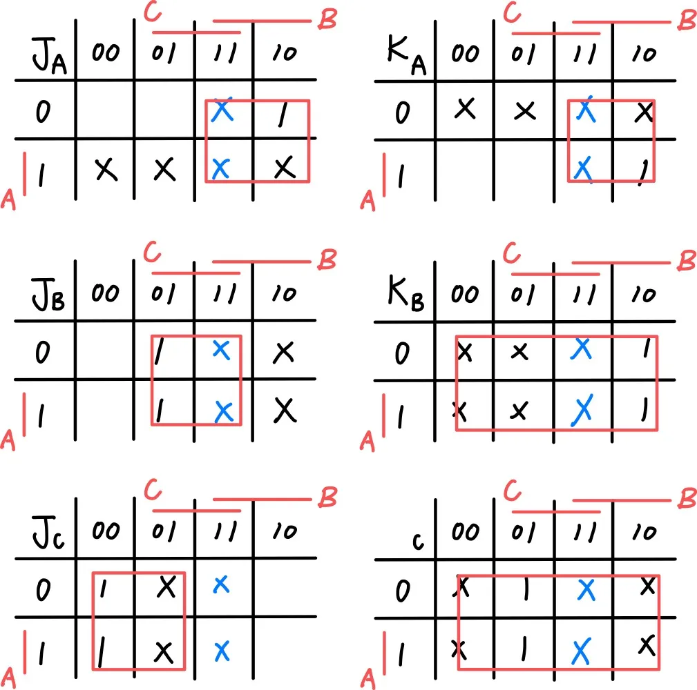
Hence, we can get the logic equation:
Then we can draw the circuit:
Verilog Implementation#
Here is a example of 4-bit Counter with Reset:
module count_4_r_v (CLK, RESET, EN, Q, CO);
    input CLK, RESET, EN;
    output [3:0] Q;
    output CO;
    reg [3:0] Q;

    assign CO = (count == 4'b1111 && EN == 1'b1) ? 1 : 0;

    always@ (posedge CLK or posedge RESET)
    begin
        if (RESET)
            Q <= 4'b0000;
        else if (EN)
            Q <= Q + 4'b0001;
    end
endmodule