Storage element introduction#
Synchronous v.s. Asychronous#
Now, we are going to discuss about sequential circuit.
But before we start, we need to define two types of sequential circuit:
| Synchronous | Asynchronous | |
|---|---|---|
| Synchronous | Yes, by a clock | No |
| When does circuit update | Upon receiving a clock pulse | Any time when an input change occurs |
| Most popular |
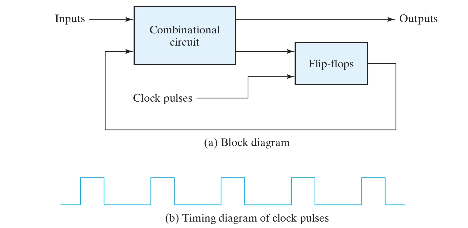
Here is a graph of synchronous circuit:
Latch#
The main idea to storage is keeping a 0-bit or a 1-bit by regenerating it in a logic loop!
Here, we introduce latch:
- the most basic storage elements
- asynchronous circuits (have no clock input)
- flip-flops can be constructed from latches
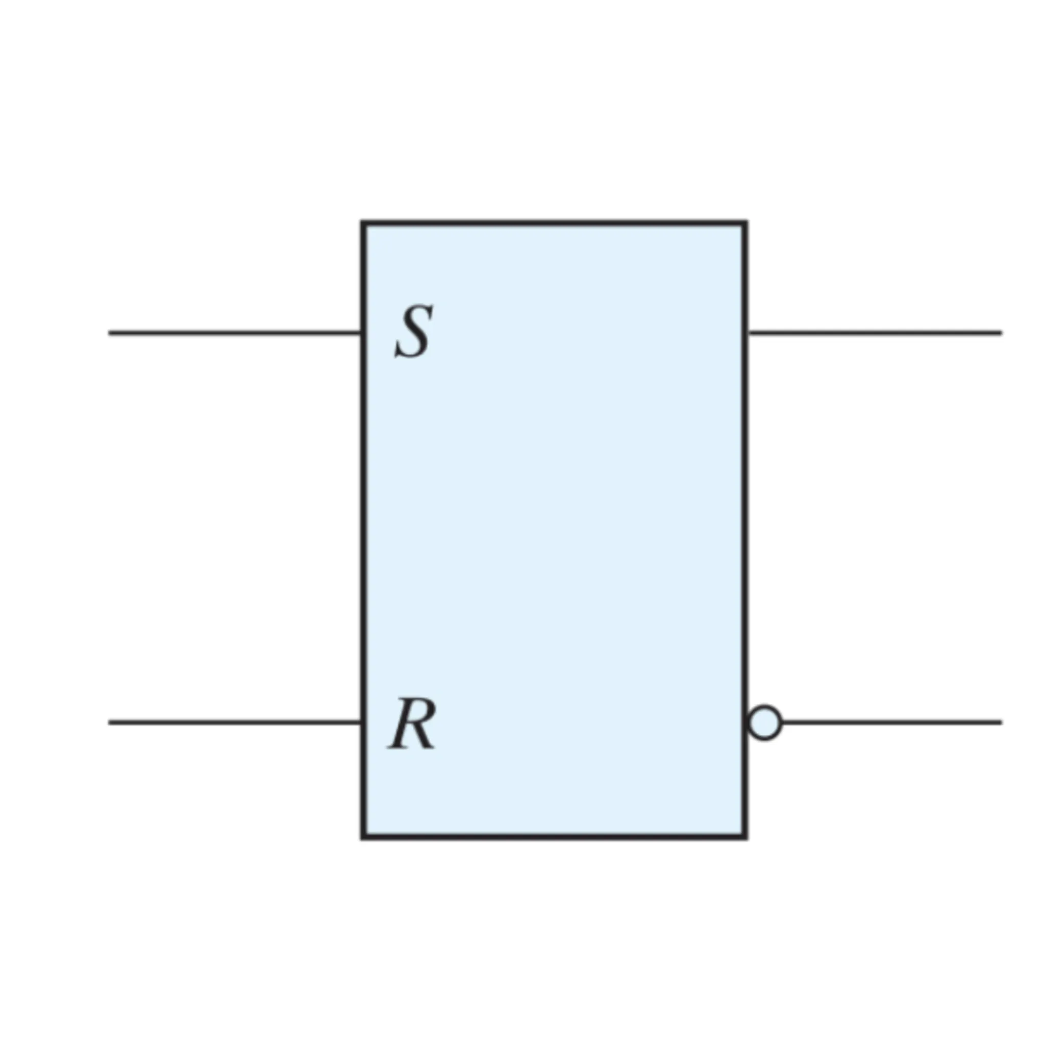
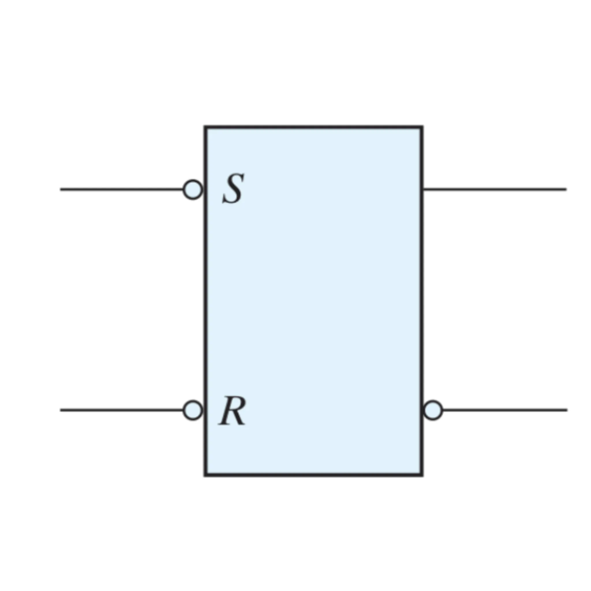
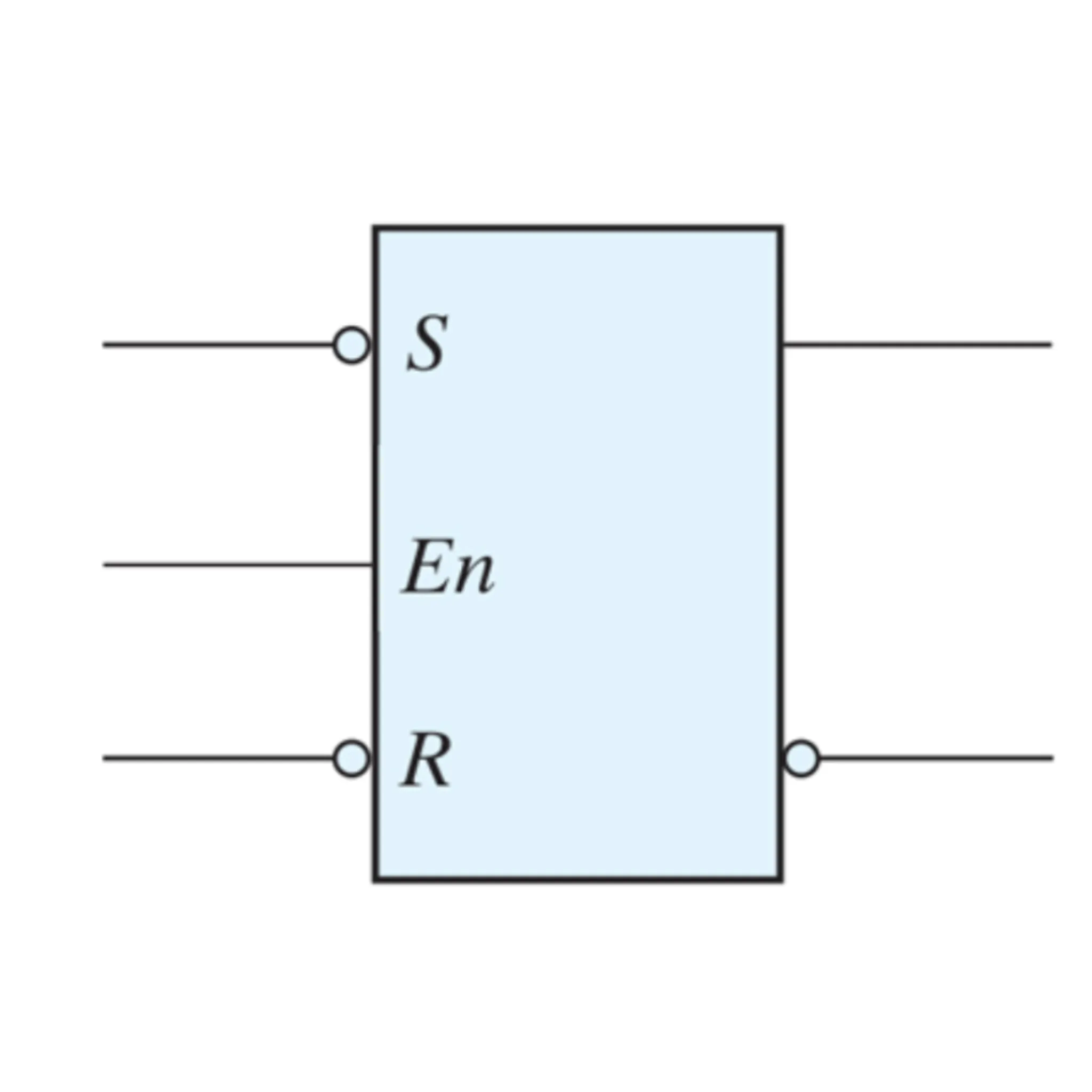
There are four types of latch:
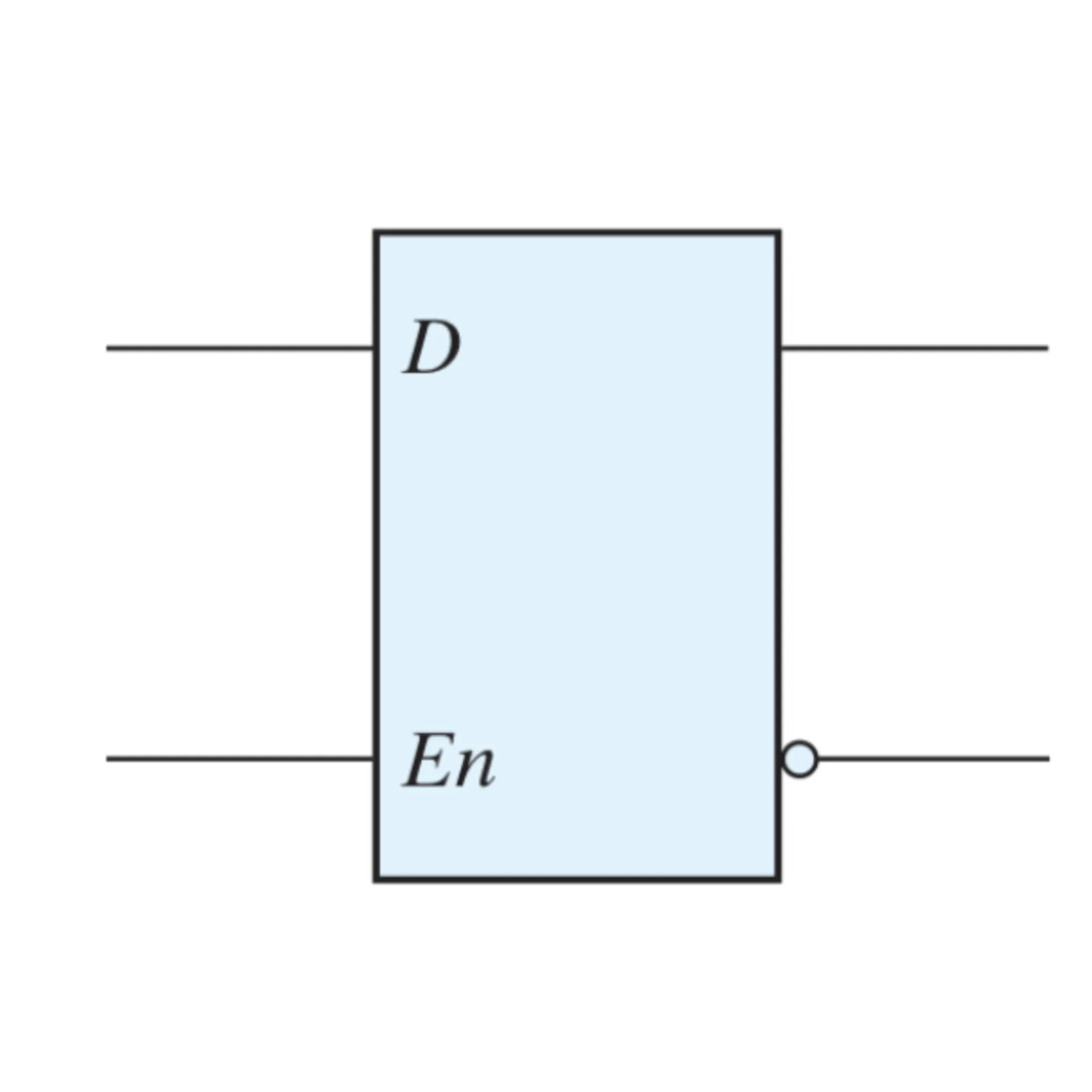
| SR | S’R’ | SR + En | D |
|---|---|---|---|
 |  |  |  |
SR latch#
Cross cupling two NOR gates:
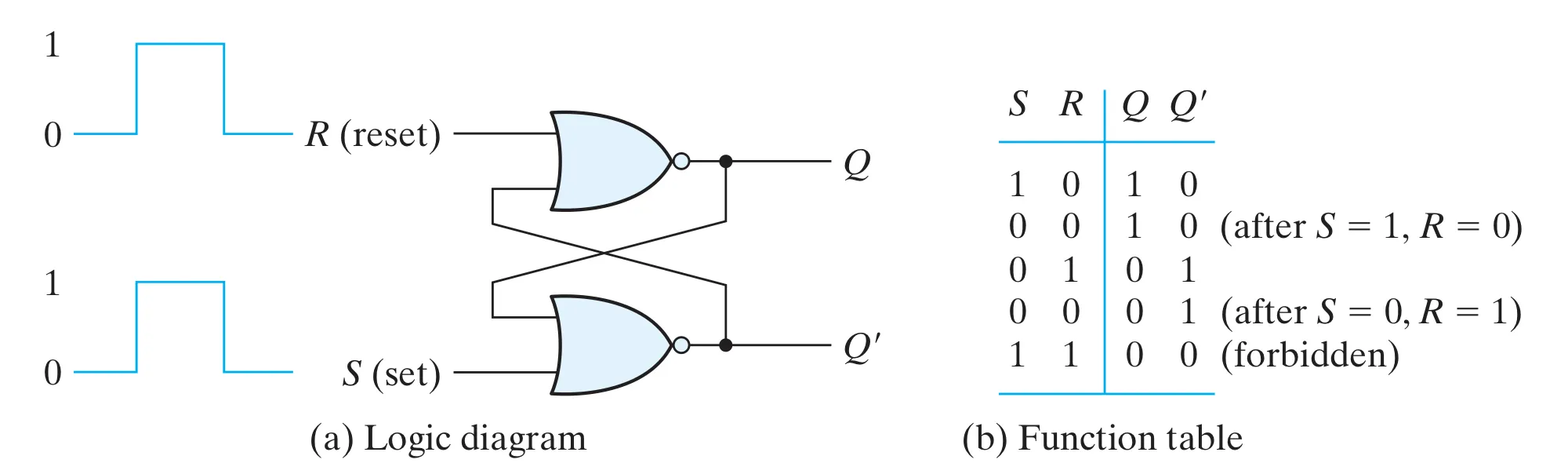 In SR latch, there are few operation:
| (next state) | ||
|---|---|---|
| 0 | 0 | (last state) |
| 0 | 1 | 0 (Reset) |
| 1 | 0 | 1 (Set) |
| 1 | 1 | Indeterminate state |
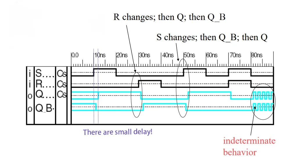
This is the logic simulation of SR latch behavior:
S’R’ latch#
Using NAND gates:
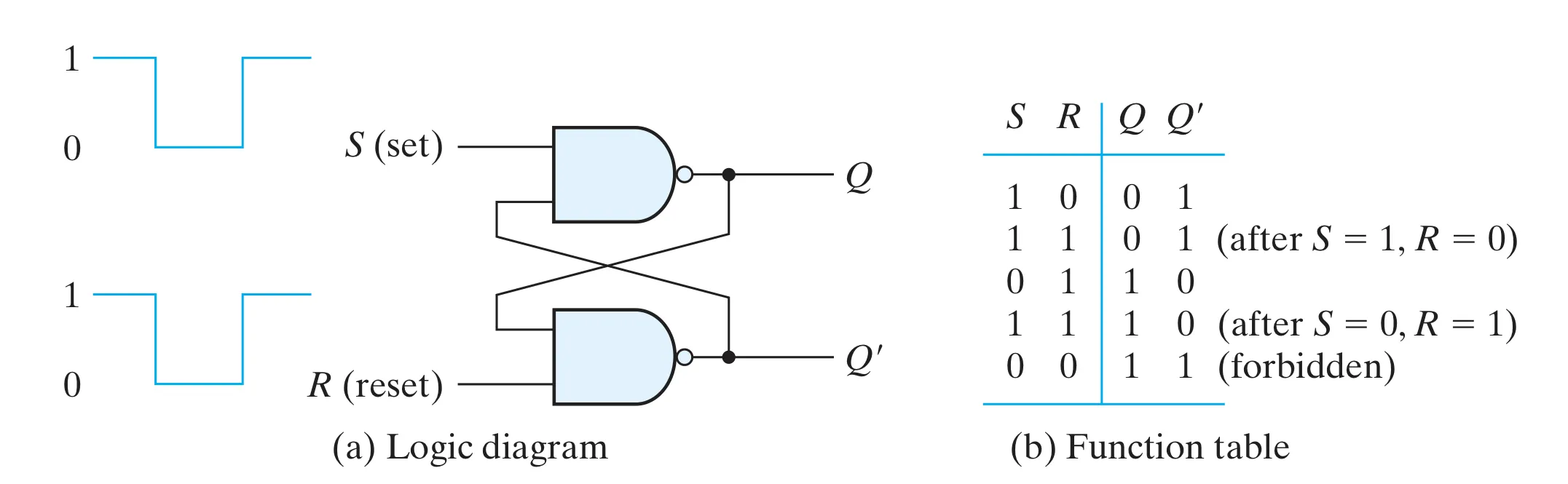 In S’R’ latch, there are few operation:
| (next state) | ||
|---|---|---|
| 1 | 1 | (last state) |
| 1 | 0 | 0 (Reset) |
| 0 | 1 | 1 (Set) |
| 0 | 0 | Indeterminate state |
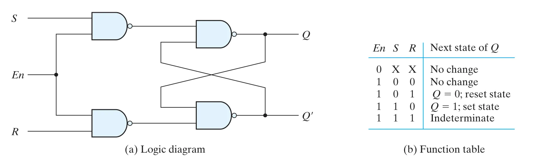
SR latch with Enable#
Now, we try to add enable ( ) on S’R’ latch:
Notice that the input has been change, so output is opposite with S’R’ latch.
D latch (Transparent latch)#
- Use only a single input to eliminate the undesirable state
- when
- no changes when
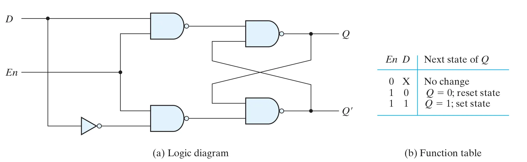 We can express D latch with Verilog:
always @(En, D) begin
    if (En == 1’b1) begin
        Q = D;
    end
endLatch v.s. Flip-flop#
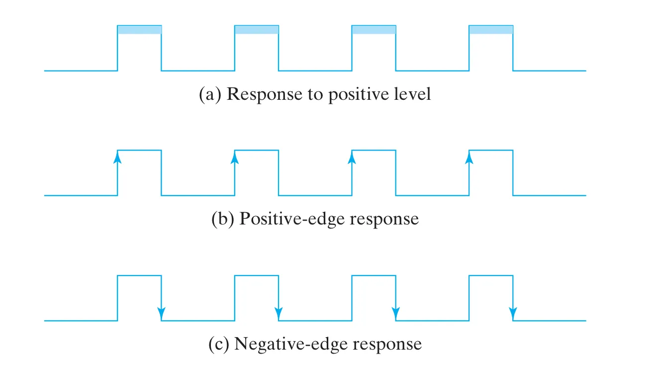
Latch is (a), level triggered and transparent as long as .
As for flip-flop, it is (b) or (c), edge triggered and the signal will hold for a peroid.
Flip-Flop (FF)#
- It is a storage element whose state cannot change more than once in a clock cycle.
- It is edge triggered, which means state transition happens only on active clock edge.
- By using flip flop, we can eliminate the multiple-transition problem.
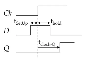
Flip-Flop timing parameters#
 Info:
Info:
- setup time minimum time for which the input data must be stable before the trigger edge
- hold time minimum time for which the input data must remain stable after the trigger edge
- propagation delay interval between the trigger edge and the stabilization of the output to its new value
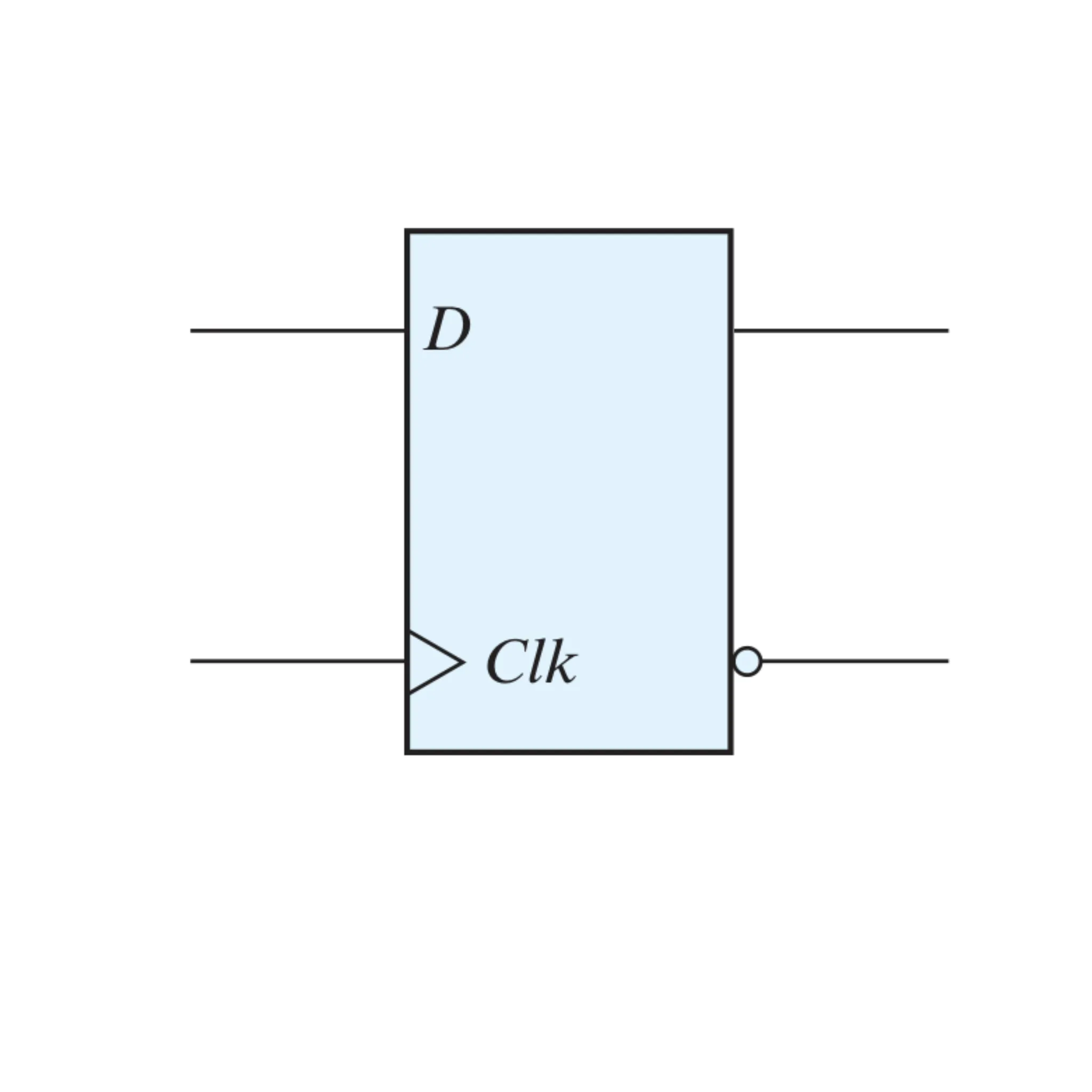
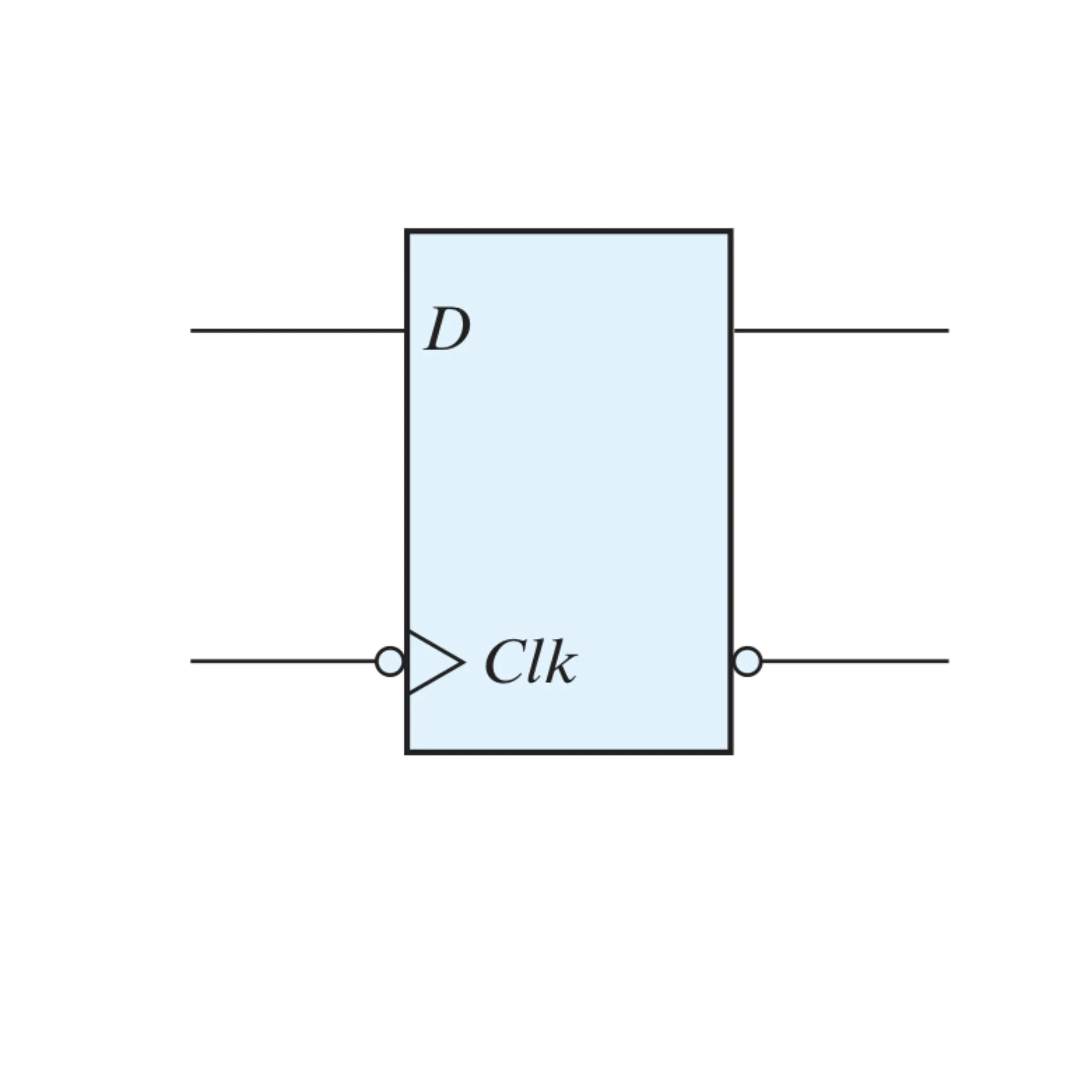
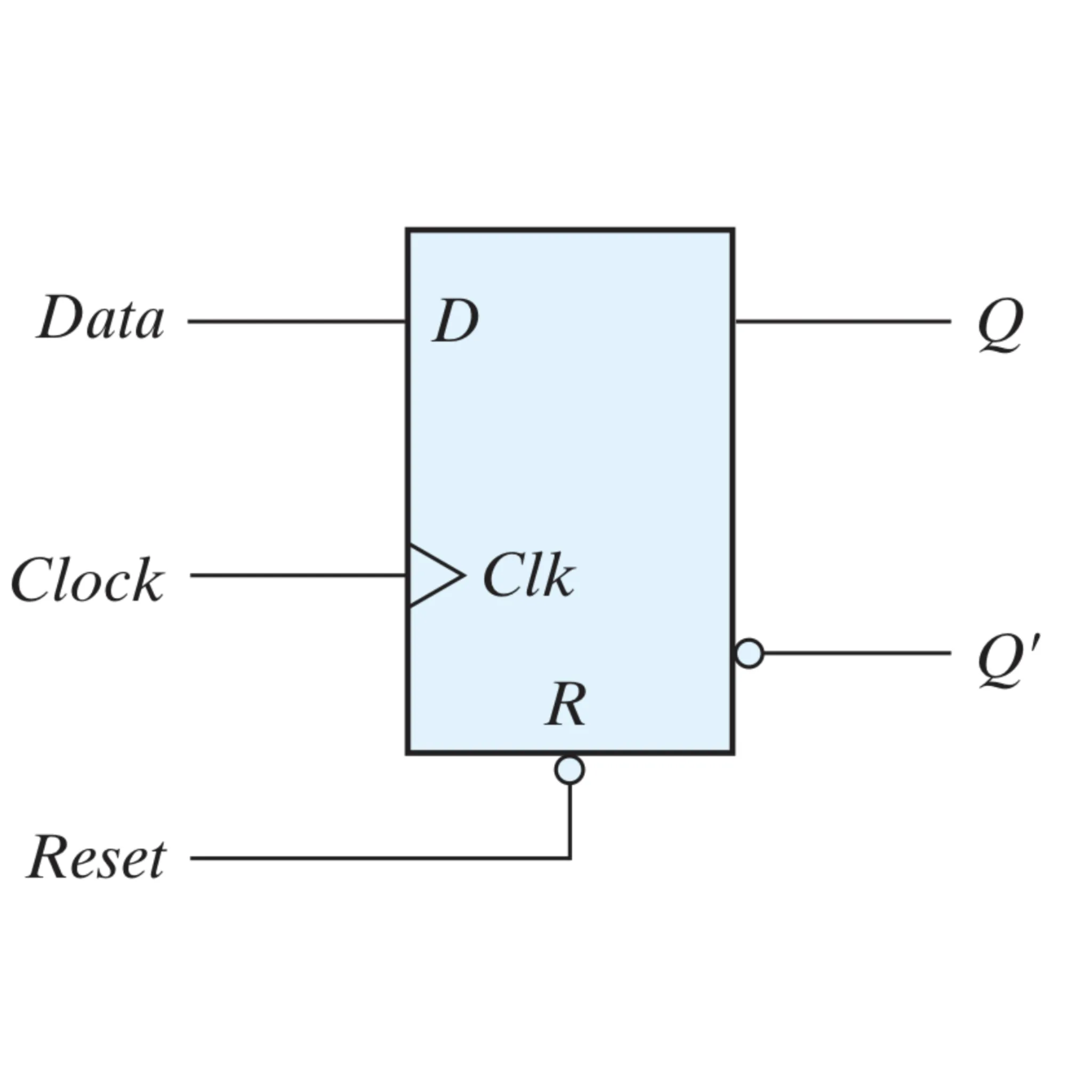
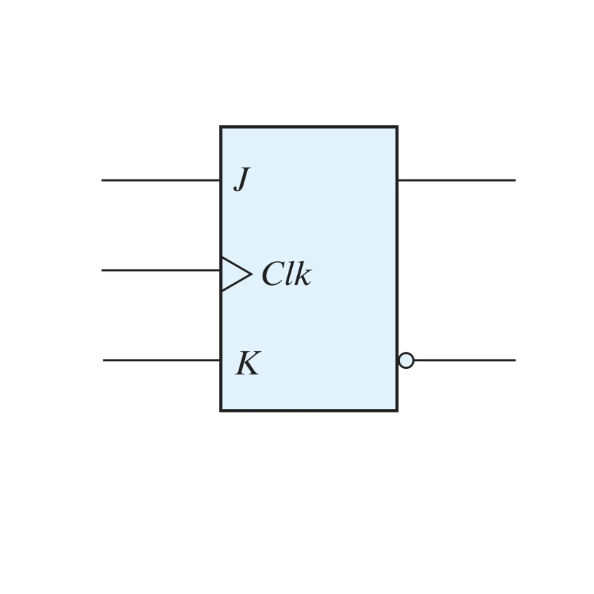
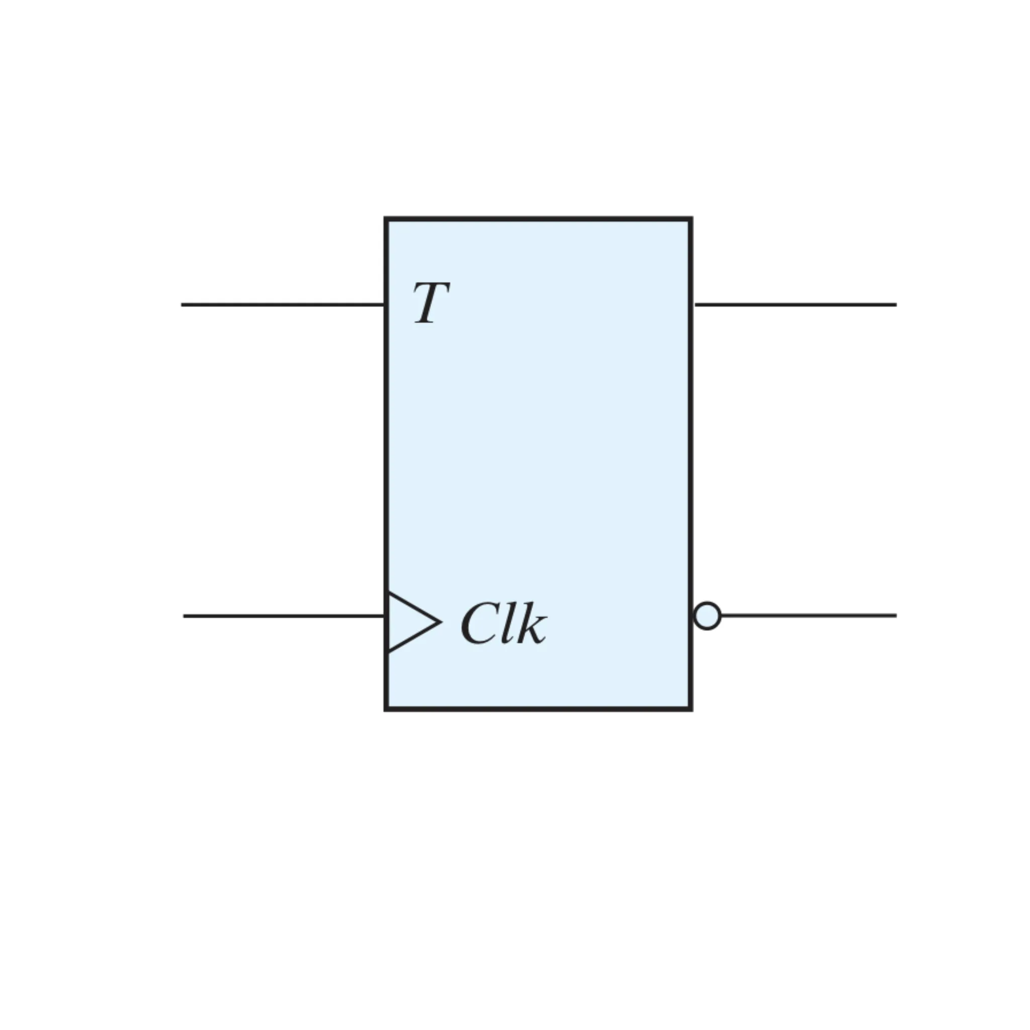
We are going to introduce flip-flop. There are four types of Flip-Flop:
| D ( Pos ) | D ( Neg ) | D + Control | JK | T |
|---|---|---|---|---|
 |  |  |  |  |
D Flip-Flop (DFF)#
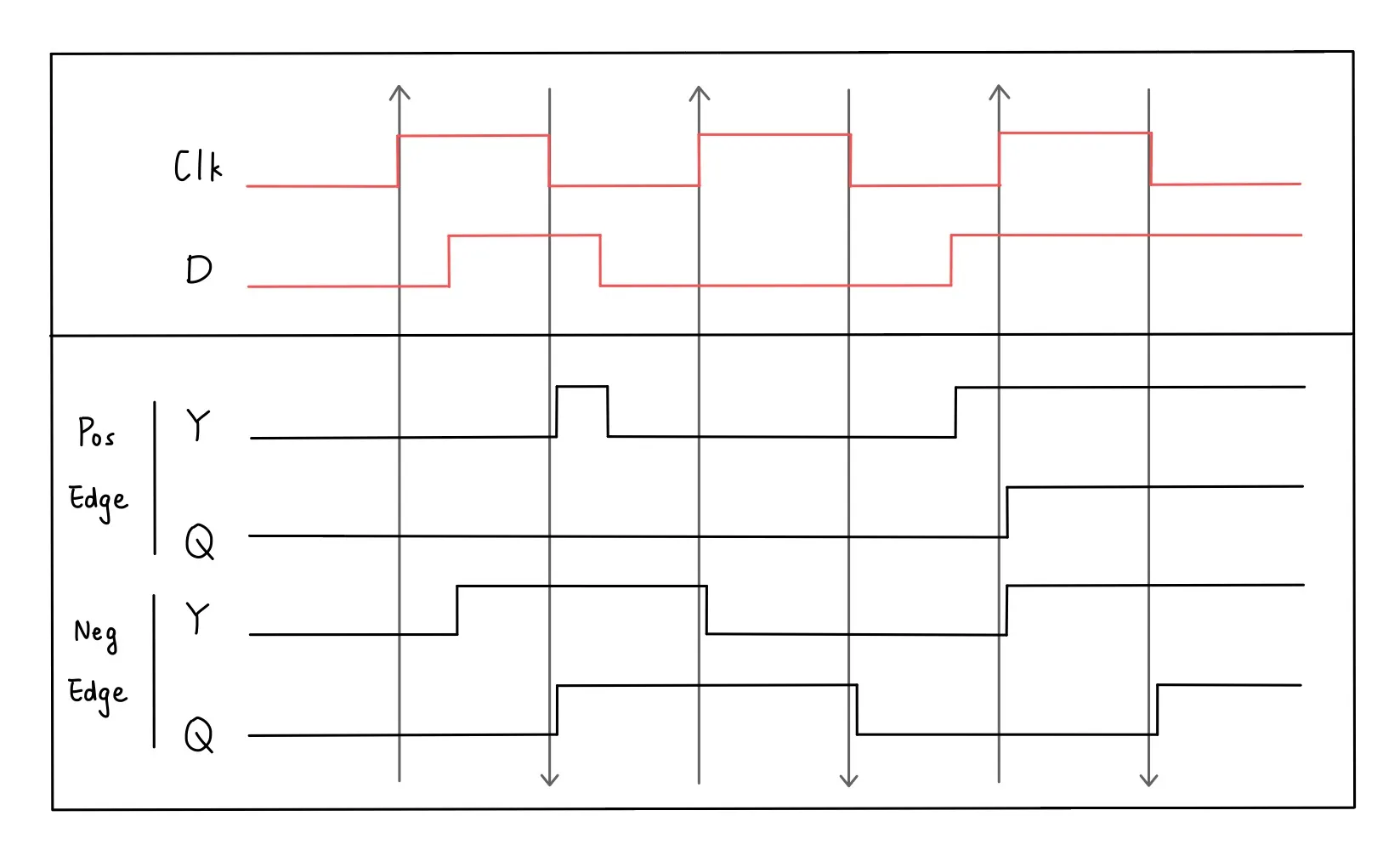
- Output changes only at active clock dege. (either positve or negative edge triggered).
- Characteristic table:
- Characteristic equation:
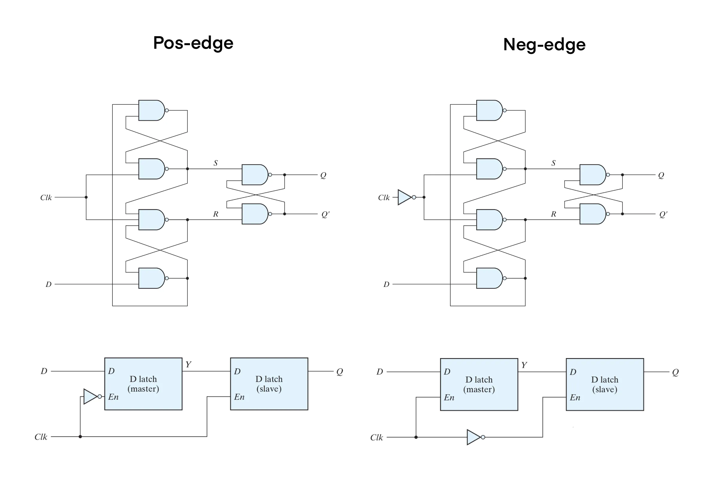 We can use the wave diagram to demonstrate the idea of D flip-flop.
We express pos-dege triggered D Flip-Flop in Verilog:
reg Q;
always @(posedge clk) begin
    Q <= D;
endD flip-flop with additional inputs#
Asynchronous Set / Reset#
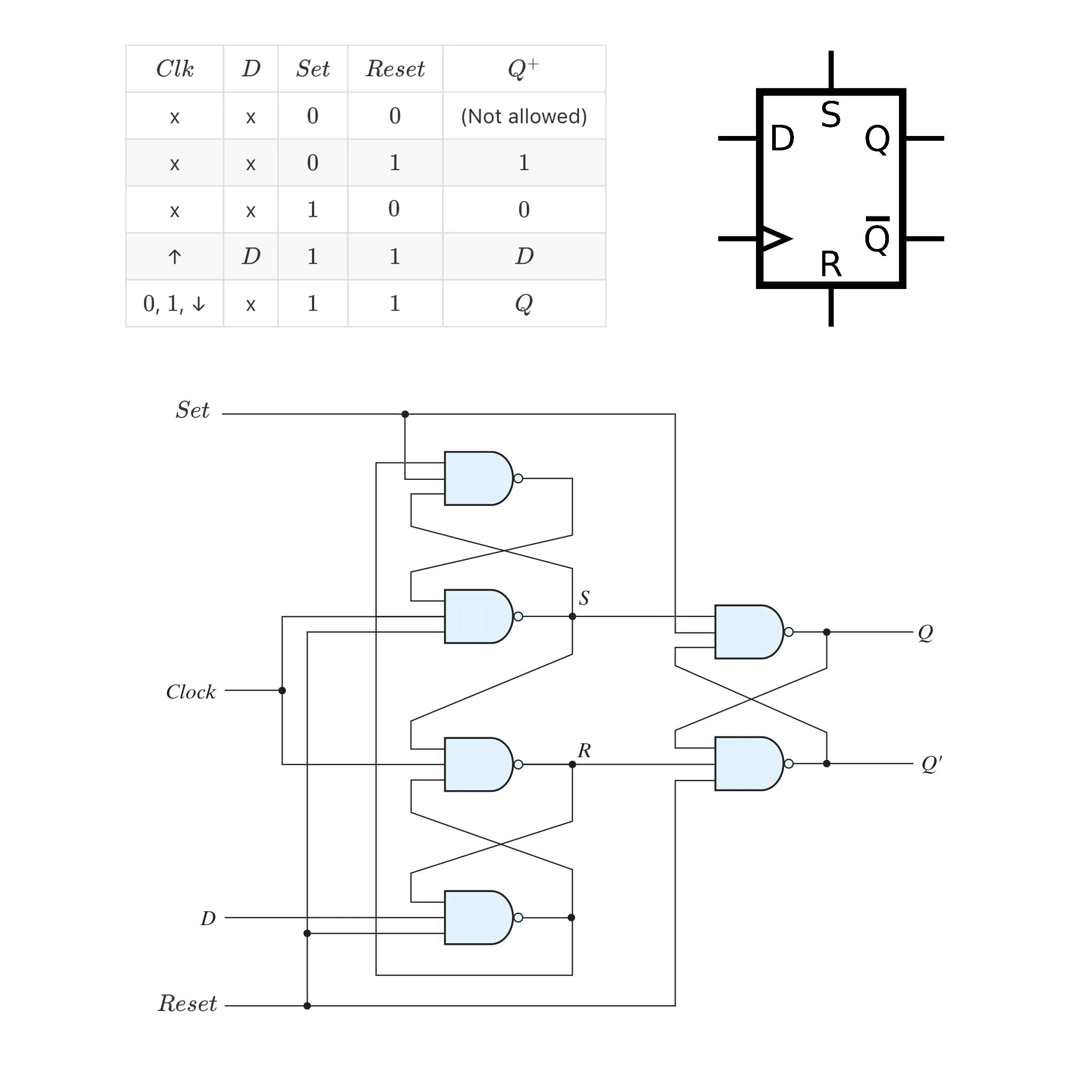
We can also describe in Verilog:
reg Q;
always @(posedge clk, posedge rst, posedge st) begin
    if (rst == 1 && st == 0)
        Q <= 0;
    else if (rst == 0 && st == 1)
        Q <= 1;
    else
        Q <= D;
    // rst == 0 && st == 0 is undefined.
endEnable input#
If , disabled, . Else, act like a normal D flip-flop, . Hence, we have:

D register with synchronous / asynchronous clear#
- Synchronous
module dff_sync_clear(
input d, clearb, clock,
output reg q
);
    always @(posedge clock) begin
        if (!clearb) q <= 1'b0;
        else q <= d;
    end
endmodule- Asyncronous
module dff_async_clear(
input d, clearb, clock,
output reg q
);
    always @(posedge clock or negedge clearb) begin
        if (!clearb) q <= 1'b0;
        else q <= d;
    end
endmoduleThe main difference is between the timing of activating always block!
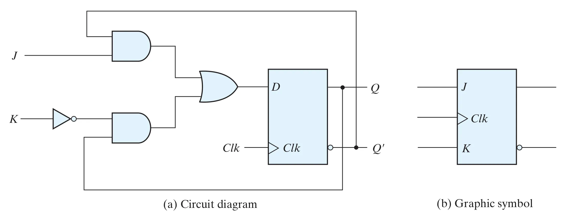
JK flip-flop#
- It can perform set, reset, and complement.
- Characteristic table:
- Characteristic equation:
This is the implementation of positive-edge triggered.
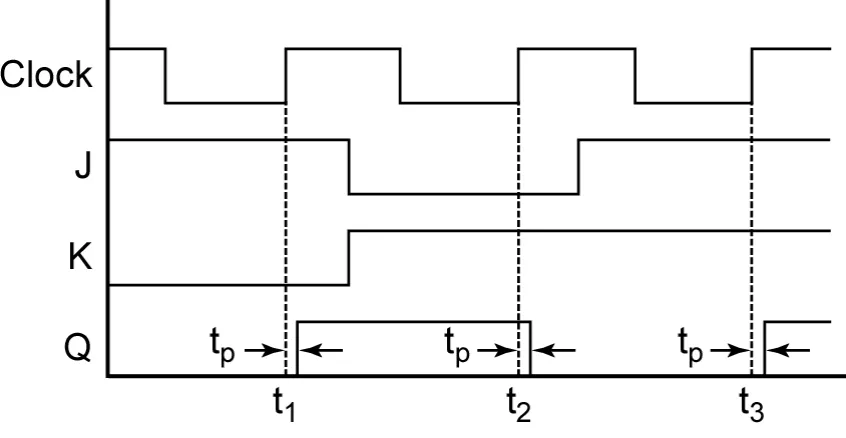
Also the wave diagram:
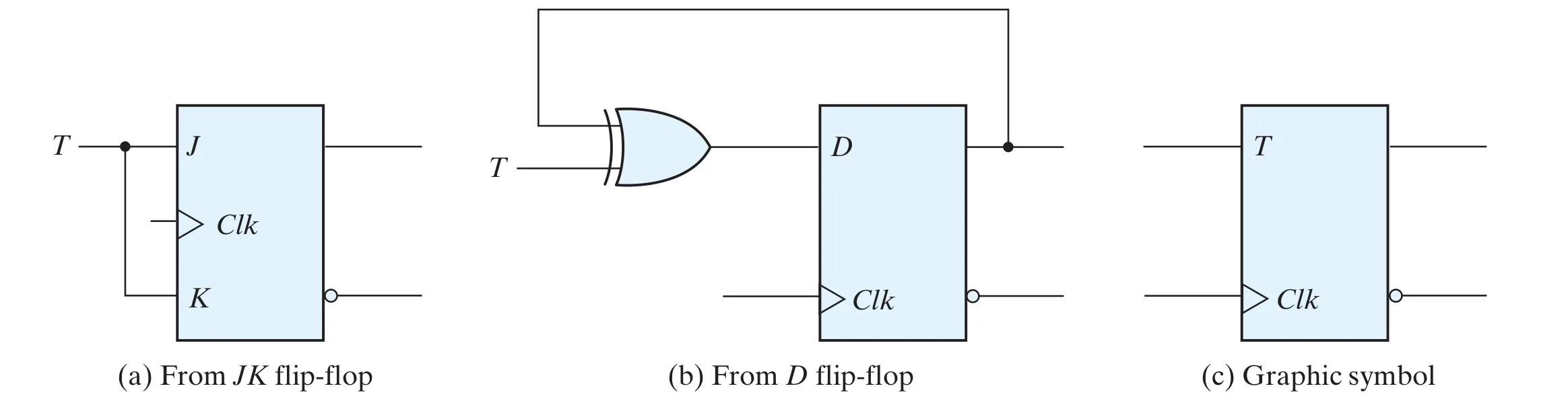
T flip-flop#
- It can only perform complement.
- Characteristic table:
- Characteristic equation:
This is the implementation of positive-edge triggered.
Characteristic equations#
| D | D+CE | JK | T |
|---|---|---|---|