Design and analysis#
Circuits#
We design logic circuits for digital system, we can seperate into two types:
Combinational circuits#
- consist of logic gates
- the outputs at any time are determined from only the present combination of inputs
- no feedbakck path
Sequential circuits#
- contain memory elements and logic gates
- the outputs are a function of the current inputs and the state of the memory elements
- the outputs also depend on past inputs
In this chapter, we will discuss combinational circuit.
Design and analysis#
Analysis#
First, we need to make sure that the circuit is combinational rather then sequential.
In other words, just check is there a feedback path.
Let’s look at the example: Info:
Converting the circuit into logic function.
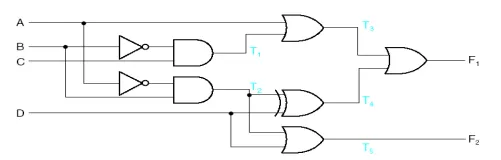
We can write the logic function gate by gate from buttom to top (see those blue dots on circuit), and we can finally get the logic function of this circuit.
Design#
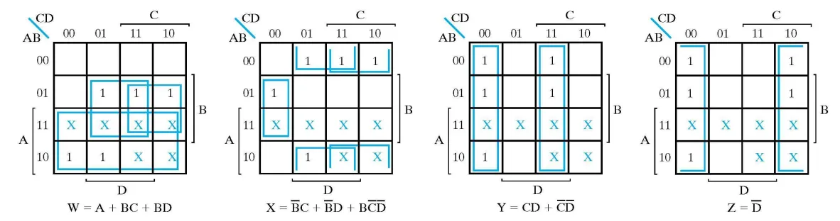
In the design process, we will start from truth table, then we use Kmap or boolean logic theorm to simplify our logic function. With advanced skill, we can do further simplification by extraction.
Without further ado, let’s look at the example:
Info:
Design a BCD-to-Excess-3 code converter.
- ps_01 : the excess-3 code of a decimal digit is the binary code of .
- ps_02 : BCD means Binary Coded Decimal.
- ps_03 : Since decimal number only have 0 ~ 9, so for 10 ~ 15, they are don’t cares.
Here is the truth table:
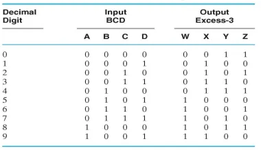
We first to 2-level simplification (Kmap simplification):
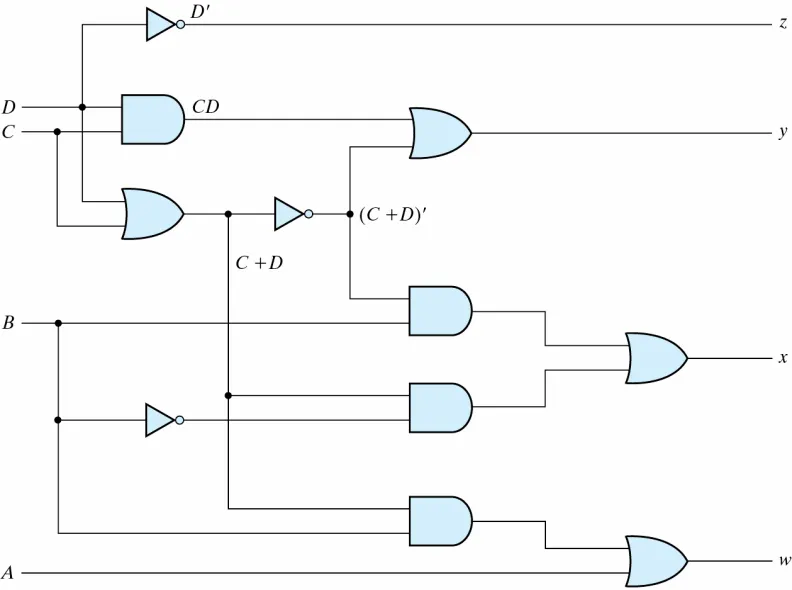
Further simplification by extraction:
Here is the circuit:
We see, in this design, we introduce a special idea — Excess-3 code, which is a very powerful tool to do addtion.