Gate-Level Minimization#
Review#
We can use sum of minterm create logic equation, and we can use it to draw a schematic.
For example, we want to determine whether the input is a prime number (), we can have the following sum of minterm Canonical Form:
Futhermore, we can draw a schematic logic diagram like this:
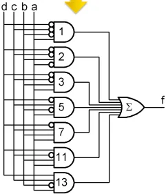 Can we optimize the number of gates that we need to use?
Gate-level Minimization#
Refers to the design task of finding an optimal gate-level implementaition of Boolean functions describing a digital circuit.
The strategy is finding a design represented as a collection of primitive logic gates and functions and the connections between them.
Two-Level Logic#
For example, SOP/POS is a two-level logic circuit.
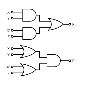 You can see both of them only have two layers.
Now, we try to simplify our boolean function, i.e., we try to write Sum Of Products (or Product Of Sum) in the simplest form.
Logic minimization method#
Using truth table and boolean algebra’s theorem to simplify our function, but it lacks specific rules.
Kamaugh map#
A diagram made up of squares, each square represents one minterm. Here is its properties:
- A simple straight forward procedure
- A pictorial form of a truth table
- Applicable if the # of variables < 7
K - Map#
- Every square that is adjacent to four directions are different in only one digit (gray code).
- For more variables, if we are able to draw a rectangle with edges that its lengths are (for example, (1, 4), (2, 8), …), then we can simplify this term.
Two variables#
For two variables, we will have minterms.
| X\Y | 0 | 1 |
|---|---|---|
| 0 | ||
| 1 |
For example, we want to simplify
then we first draw a K-map:
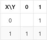 Second, we draw valid rectangles to simplify:
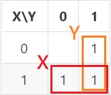
So the following result will be:
Three variables#
For three variables, we will have minterms.
| X\YZ | 00 | 01 | 11 | 10 |
|---|---|---|---|---|
| 0 | ||||
| 1 |
For example, we want to simplify
so first we draw K-map:
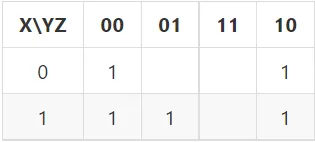 Second, still draw valid rectangle, here, we can add spporting description (gray text)
to figure out what is the outcome of any rectangle:
Second, still draw valid rectangle, here, we can add spporting description (gray text)
to figure out what is the outcome of any rectangle:
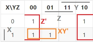
So the following result will be:
Four variables#
For four variables, we will have minterms.
| WX\YZ | 00 | 01 | 11 | 10 |
|---|---|---|---|---|
| 00 | ||||
| 01 | ||||
| 11 | ||||
| 10 |
For example, we want to simplify
so first we draw K-map:
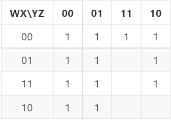
Second, still draw valid rectangle, still using spporting description (gray text)
to figure out what is the outcome of any rectangle:
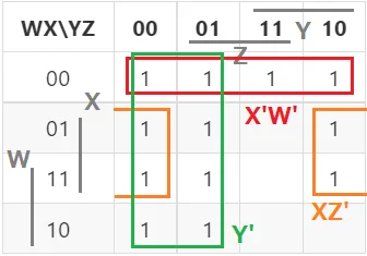
So the following result will be:
Extra definition#
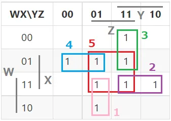
Since the rectangle we draw may be arbitrary, so we have these few definitions: Info:
- Minterm A product term that includes every input variable or its complement. It is actually every square on K-map.
- Implicant A product term that if true implies the function is true. Shortly speaking, it is the rectangle we draw.
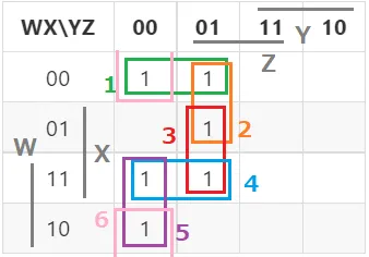
- Prime Implicant (PI) An implicant that cannot be made any larger and still be an implicant.
- Essential Prime Implicant (EPI) The only prime implicant that contains a particular minterm of the function.
- Redundant Prime Implicant (RPI) The prime implicants for which each of its minterm is covered by some essential prime implicant.
- Selective Prime Implicant (SPI) The prime implicants for which are neither essential nor redundant prime implicants.
Here, lets look at some examples:
Strategy of cover a function#
Success:
- Start with an empty cover.
- Add all EPI to the cover.
- For each remaining uncovered minterm, add the largest implicant to cover it.
With this strategy, we can obtain Good cover, which is no guarantee it is the lowest-cost cover.
Don’t cares#
Sometimes, the value of some function is not specified for certain combinations of variables, we call this function Incompletely Specified Function. The don’t care conditions can be utilized in logic minimization. (use to represent) Let’s look at an example:
Simplify the following function:
First, draw a K-map:
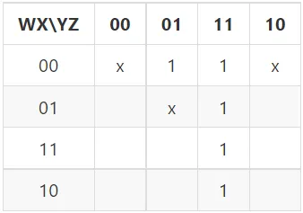 Remember, a don’t care means that we can regard it as 1 or 0, so we can circle it or not.
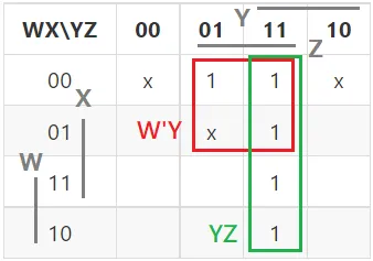 What’s more, we can also circle like this:
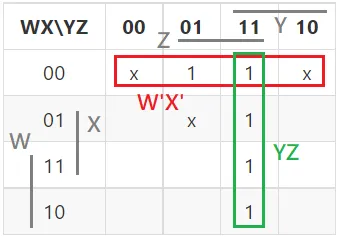 We know that , but in this situation(with don’t cares), both method is corrent for simplifying this function.
Hence, we can get the simplified function:
We know that , but in this situation(with don’t cares), both method is corrent for simplifying this function.
Hence, we can get the simplified function:
Simplified POS#
As we can see, using K-map method we can obtain a simplified output in terms of SOP, so if we want to get the simplified function in terms of POS, we need to do this: Info:
We want to simplified in terms of POS. Using K-map to find the simplified SOP of , the add a negation, then we will have a simplified in terms of POS.
In shorts, we can do K-map on F but rather than gathering 1, we gathering 0. Here is an example: we want to simplify in terms of POS.
First , we draw K-map, but this time we focus on 0.
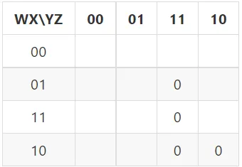 Thus, we can draw a circle like this:
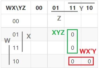 So we can rewrite :
We add a negation on it, then we will have:
Then we have the answer!
Example — Prime Detector#
Simplify#
As we have in the beginning, we want to design a prime detector for ~ , we can have the SOP form:
Thus, we use Kmap to simplify our function.
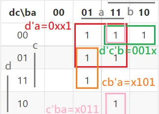 Anything is the same as the Kmap above, but here is an implement detail.
In verilog, we will use 0, 1, x to represent the situation of each bit, so for any implicant, we can write it as the situation for each bit.
So we can write the function as:
Then we can design a circuit to implement it!
Circuit diagram#
First, lets try to use AND-OR gate.
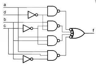
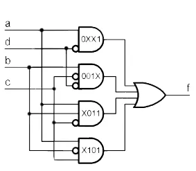 In practice, CMOS gates are always inverting,
so the real circuit might use NAND-NAND design instead of AND-OR.
In practice, CMOS gates are always inverting,
so the real circuit might use NAND-NAND design instead of AND-OR.
Multi-output circuit optimization#
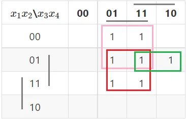
As we mentioned above, we will try to get as large implicant as possible, but sometimes, if we have multiple output, then non-prime implicants may be shaerd advantageously.
Here is an example: Consider these two function:
If we optimize independently, we will have the following K-map:
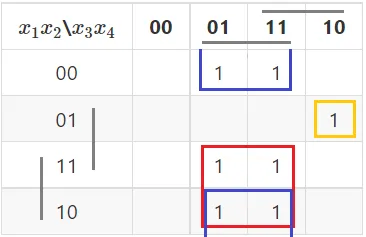
But if we consider both circuit, then we may optimize by sharing some implicants:
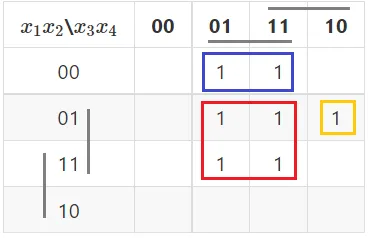
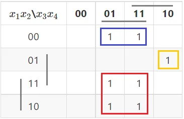
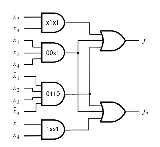
We can see that both function can share blue implicant (00x1) and yellow implicant (0110),
so we can reduce our circuit like this:
In next chapter, we will introduce more about gates.