Iterative systems#
Including two types : Arithmetic circuits and Magnitude comparators.
Arithmetic circuits#
We will introduce some basic circuits to do calculation.
Half Adder#
A half adder performs addition of two bits:
- 2 input bits : ,
- 2 output bits : (carry), (sum)
Here is the truth table :
| x | y | C | S |
|---|---|---|---|
| 0 | 0 | 0 | 0 |
| 0 | 1 | 0 | 1 |
| 1 | 0 | 0 | 1 |
| 1 | 1 | 1 | 0 |
Implementation#
Logic function#
Schematic Diagram#
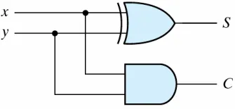
Verilog Description#
// half adder
module HalfAdder(a,b,c,s);
    input a,b ;
    output c,s ; // carry and sum
    wire s = a ^ b ;
    wire c = a & b ;
endmoduleFull Adder#
A full adder is for adding three bits.
- 3 input bits : , : two significant bits ( ) : the carry bit from the previous lower significant bit
- 2 output bits : ( ),
Here is the truth table :
| x | y | z | C | S |
|---|---|---|---|---|
| 0 | 0 | 0 | 0 | 0 |
| 0 | 0 | 1 | 0 | 1 |
| 0 | 1 | 0 | 0 | 1 |
| 0 | 1 | 1 | 1 | 0 |
| 1 | 0 | 0 | 0 | 1 |
| 1 | 0 | 1 | 1 | 0 |
| 1 | 1 | 0 | 1 | 0 |
| 1 | 1 | 1 | 1 | 1 |
Implementation#
Logic function#
First, start from Kmap.
-
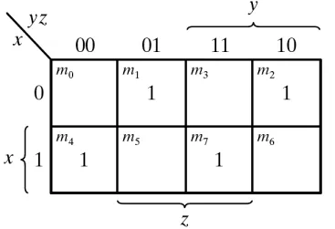
-
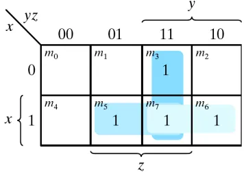 Futhermore, a full adder can be implemented with two half adders and one OR gate,
we denote a half adder to be , and each half adder has s and c : and .
Futhermore, a full adder can be implemented with two half adders and one OR gate,
we denote a half adder to be , and each half adder has s and c : and .
\begin{align} xy+yz+zx &= xy+(x+x’)yz+x(y+y’)z\ &=xy+xyz+x’yz+xyz+xy’z\ &=xy(1+z)+(x’y+xy’)z\ &=xy+(x\oplus y)z \end{align}
#### Schematic Diagram - Logical  - From half adders   #### Verilog Description ```verilog= // full adder - logical module FullAdder2(a, b, cin, cout, s); input a, b, cin; output cout, s; wire s = a ^ b ^ cin; wire cout = (a & b) | (a & cin) | (b & cin); // majority endmodule ``` ```verilog= // full adder - from half adders module FullAdder1(a, b, cin, cout, s); input a, b, cin; output cout, s; // carry and sum wire g, p; // generate and propagate wire cp; HalfAdder ha1(a, b, g, p); HalfAdder ha2(cin, p, cp, s); assign cout = g | cp; endmodule ``` ## Ripple Carry Adder - Add two $n$-bit numbers - Like addition by hand, progress from leastsignificant digit to most-significant digit. - If a carry is produced in position $i$, it is added to the operands in position $i+1$. - A ripple carry adder is formed by cascading $n$ full adders.  We can implement it by gate level and dataflow level: ```verilog= module Half_Adder (a, b, c, s); input a, b; output c, s; wire c, s; xor find_s (s, a, b); and find_c (c, a, b); endmodule module Full_Adder (a, b, cin, cout, s); input a, b, cin; output cout, s; wire cout, s; wire tempc, temps, tempcc; Half_Adder first_adder (a, b, tempc, temps); Half_Adder second_adder (temps, cin, tempcc, s); or find_cout (cout, tempc, tempcc); endmodule module ripple_carry_adder (in0, in1, out, cout,s_overflow,u_overflow); // declare input signals input [3:0] in0; input [3:0] in1; // declare output signals output [3:0] out; output cout; output s_overflow; output u_overflow; // here is your design wire [3:0]out; wire cout, s_overflow, u_overflow; wire [3:1]carries; Full_Adder FA1 (in0[0], in1[0], 0, carries[1], out[0]); Full_Adder FA2 (in0[1], in1[1], carries[1], carries[2], out[1]); Full_Adder FA3 (in0[2], in1[2], carries[2], carries[3], out[2]); Full_Adder FA4 (in0[3], in1[3], carries[3], cout, out[3]); xor find_soverflow (s_overflow, cout, carries[3]); assign u_overflow = cout; endmodule ``` ## Fast adder  ## Addition and subtraction We've been dealing with **Unsigned** numbers, so we haven't considered about negative number and subtraction, which is the scope of **Signed** numbers. Hence, it's time to take a look. **Warning:** The following content will use **2's complement form**, if you are not familar with it, please go to [here](https://hackmd.io/@tropical08842/SkoSlpxec/%2FaXLij1WTT2KIsMY1agroTw). ### Addition - Add every bit (including the sign bits). - Discard any carry out of the sign bit position. Here are some example :  ### Subtraction - $A-B=A+(-B)$ - So we just need to convert the latter number into its 2's complement form, then add them up. ### Overflow - Since we only have $n$ bits, the storage is limited. - Since no matter the operation is addition or subtraction, they will all come down to addition. So **we only discuss overflow in addition.** Then we have the question: $$Q: What situation will overflow? (A: Too big or too small)$$ By observation, we know that overflow will only happens when adding two **very large** positive number or two very **small negative** number, then we seperate into two cases:  For convenience, from now on we denote **the most significant bit** be $n$-th bit. We can obtain the logic function to detect whether the addtion is overflow:Overflow = A_nB_nS_n’+A_n’B_n’ S_n
**Detail explanation:**  #### **Case_01** : positive + positive = negative More specifically, if $A_{n}$ and $B_{n}$ are both $0$ ( positive number ), and after adding, $S_{n}$ become $1$ ( then the sum will be **negative** number ), then it will overflow. #### **Case_02** : negetive + negative = positive Similarly, if $A_{n}$ and $B_{n}$ are both $1$ ( negative number ), and after adding, $S_n$ become $0$ ( then the sum will be **positive** number ), then it will overflow. Hence, we can have:Overflow = A_nB_nS_n’+A_n’B_n’ S_n
Overflow=C_n\oplus C_{n-1}
**Detail explanation:** We can discuss into two cases: #### Cases_01 : $C_n = 0$ ( Which is equivalent to the case of $A_{n}B_{n}=0,0$ ) If the carry out of $n$ bit is $0$, they must both be **positive** number. -> $(A, B, C_{in}) = (0, 0, 0)$ or $(0, 0, 1)$ will both cause $C_{out} = 0$. Then the case will be overflow if the $n-1$ digit ouput a carry out ( $C_{n-1} = 1$ ). -> Since the sum of these two number will be **negative**. #### Cases_02 : $C_n = 1$ ( Which is equivalent to the case of $A_{n}B_{n}=1,1$ ) If the carry out of $n$ bit is $1$, they must both be **negative** number. -> $(A, B, C_{in}) = (1, 1, 0)$ or $(1, 1, 1)$ will both cause $C_{out} = 1$. Then the case will be overflow if the $n-1$ digit doesn't ouput a carry out ( $C_{n-1}=0$ ). -> Since the sum of these two number will be **positive**. Thus, we can combine those two condition and get:\begin{align} Overflow &= C_n’C_{n-1}+C_nC_{n-1}’ \ &=C_n\oplus C_{n-1} \end{align}
### Implementation : 4-bit Add-Subtractor We need another input $K$ to determine wether we are doing Addition of Subtraction. **Info:**K=0 if we want to compute A+B \ K=1 if we want to compute A-B=A+B’+1
Yes, by the definition of 2's complement, $-B=B'+1$. Hence, we can have our logic function of $B$ determined by $K$:\begin{align} f_B(K)&=K(B’+K)+K’(B+K’)\ &=KB’+K+K’B+K’\ &=KB’+K’B\ &=K\oplus B \end{align}
f=A+f_B(K)=A+(K\oplus B)
Then we can construct our schematic circuit:  ## Decimal Adder - In each stage, we add two BCD digits. ( 9 inputs : two BCD digits and one carry-in ) - We use a **4-bit binary adders** and a **binary to BCD conversion** to implement.  Now we need to implement the conversion part. ### Binary to BCD  Remember that C in BCD sum means the higher number is 1 or 0 (here is 10 or 0). By observation, we can see that for Decimal number that is larger than 9, we need to do modification to get correct BCD sum. - $C$ : for number that is lager then $9$, $C = 1$, in other words: $$C=K+Z_8Z_4+Z_8Z_2$$ - As for other bits ($S_8, S_4, S_2, S_1$), we just add **6** to the binary sum to convert to the correct BCD representation when $C = 1$. **Why is add 6:**The binary repesentation of 10+n will becomes 0+n.
The binary repesentation of 10+n will becomes 16+n.
Thus it is easy to see that it add 6. Hence, we can draw the block diagram:  It use $C_{out}$ as the input of $6$ to determine it adds $0$ or $6$. # Magnitude comparators The main idea is to determine the two inputs $A$, $B$ are whether $A>B$, $A=B$, $A<B$. First, we assume the input$A$, $B$ are represent in four bits:A=A_3A_2A_1A_0 \ B=B_3B_2B_1B_0
First, we define $X_i:=A_iB_i+A_i'B_i'=(A_i\oplus B_i)'$, which means that whether the $i$-th bit is the same. Then we can get its logic expression for these three outputs: $$\begin{cases} A=B &: &X_3X_2X_1X_0 \\ A>B &: &A_3B_3'+X_3A_2B_2'+X_3X_2A_1B_1'+X_3X_2X_1A_0B_0' \\ A<B &: &A_3'B_3+X_3A_2'B_2+X_3X_2A_1'B_1+X_3X_2X_1A_0'B_0 \end{cases}Then we can draw the circuit:
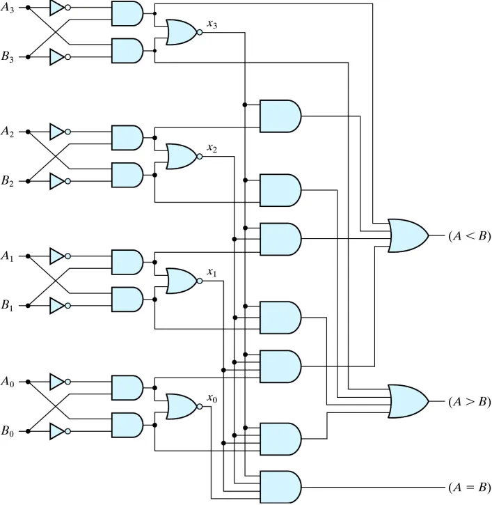 We can use Verilog to implement:
\\Behavioral level
module magnitude_comparator(a, b, a_lt_b, a_eq_b, a_gt_b);
    parameter k = 4;
    input [k - 1:0] a, b;
    output a_lt_b, a_eq_b, a_gt_b;
    assign a_lt_b = (a < b);
    assign a_eq_b = (a == b);
    assign a_gt_b = (a > b);
endmodule