Combinational building blocks#
A few types of logic circuit are often used as building blocks in larger design:
Decoder (binary to one-hot)#
One-Hot representation#
- Represent a set of elements with bits
- Exactly one bit is set
- Example – to encode numbers 0-7
| Binary | One-hot |
|---|---|
| 000 | 00000001 |
| 001 | 00000010 |
| 010 | 00000100 |
| 011 | 00001000 |
| 100 | 00010000 |
| 101 | 00100000 |
| 110 | 01000000 |
| 111 | 10000000 |
n-to-m decoder#
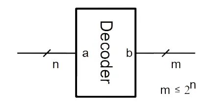
- input variables; up to output lines( )
- binary to one-hot decoder
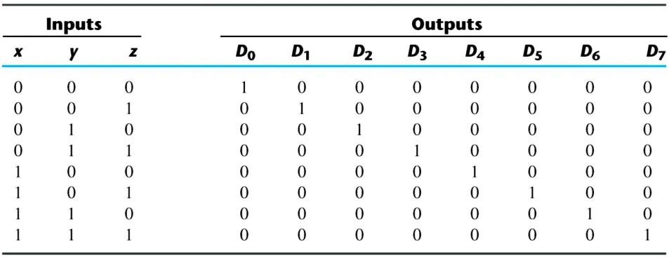
This is the description of decoder by Verilog:
// a - binary input (n bits wide)
// b - one hot output (m bits wide)
module Dec(a, b);
    parameter n = 2;
    parameter m = 4;
    input [n - 1:0] a;
    output [m - 1:0] b;
    wire [m - 1:0] b = 1 << a;
endmoduleWith parameter in a module (Parameterized Module), we can decide those parameters while instantiation.
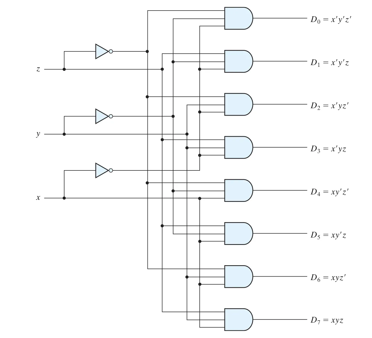
Dec dec2to4 (a, b); // Default parametersDec # (3, 8) dec3to8 (a, b); // Overriding the parametersDec # (.n(4), .m(10)) dec4to10 (a, b); // An other method to overridingThis is the circuit of a 3 to 8 decoder:
Decoder with Enable input#
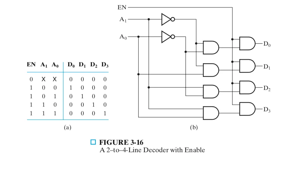
If the Enable is , output , if the Enable is , output the normal output.
Decoder Tree#
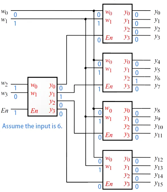
It is a 4-to-16 decoder made by 2-to-4 decoder.
Utility#
Info:
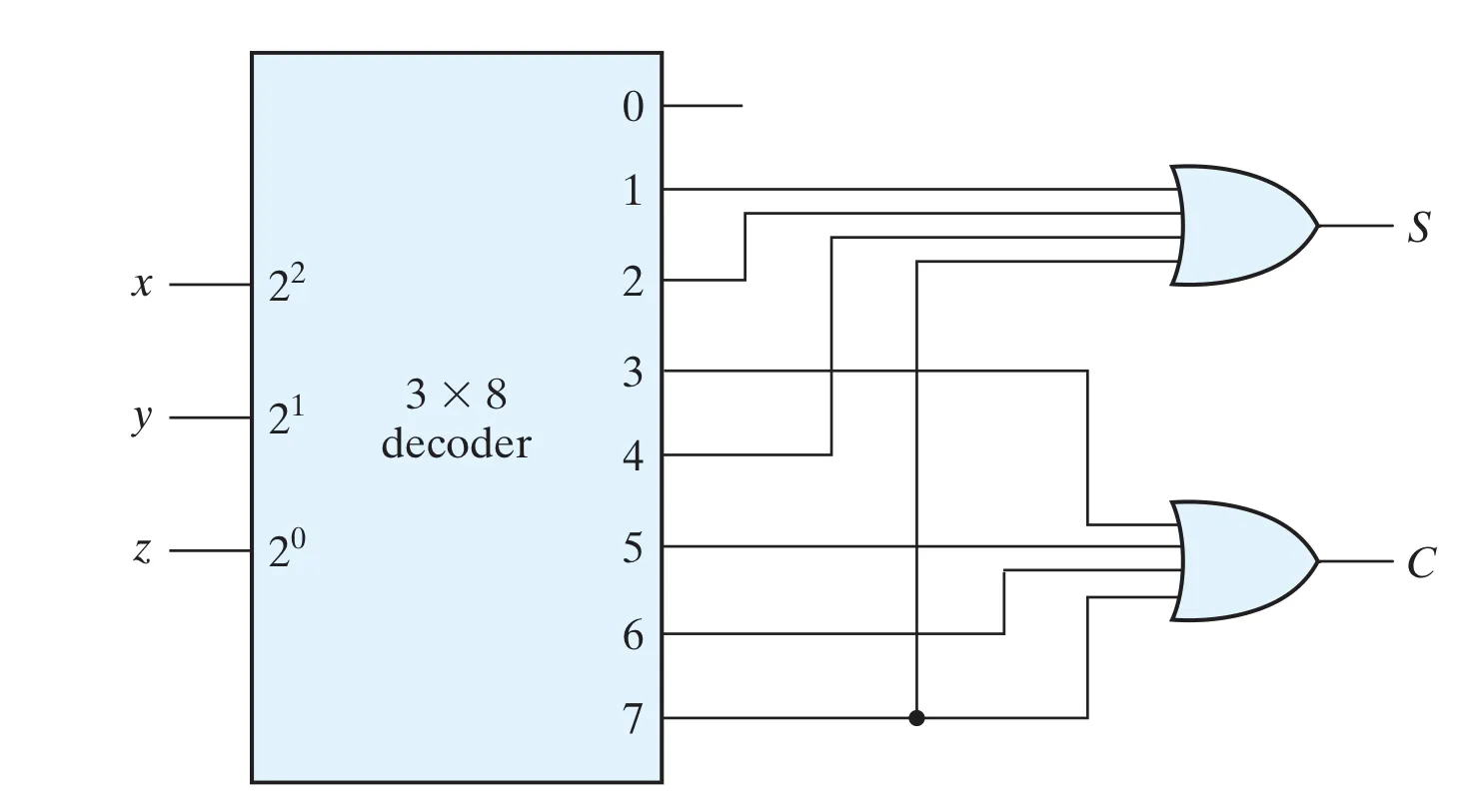
Each output of a decoder is a minterm, so we can use a decoder and a external OR gate to implement any Boolean function.
Example 1#
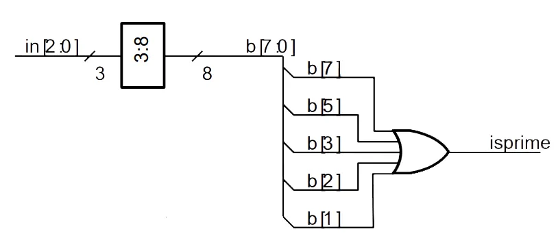
Implement a Prime Number Detector for 0 to 8 with decoder.
module Primed(in, isprime);
    input [2:0] in;
    output isprime;
    wire [7:0] b;
    // compute the output as the OR of
    // the required minterms
    wire isprime = b[1] | b[2] | b[3] | b[5] | b[7];
    // instantiate a 3->8 decoder
    Dec #(.n(3), .m(8)) d(.a(in), .b(b));
endmoduleExample 2#
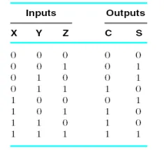
Implement a full adder with decoder. Remind that .
Encoder (one-hot to binary)#
n-to-m encoder#
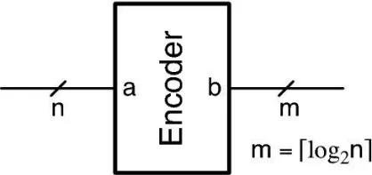
- An encoder provides the inverse function of a decoder
- Encoder converts an n-bit one-hot input signal to an m-bit binary-encoded output signal
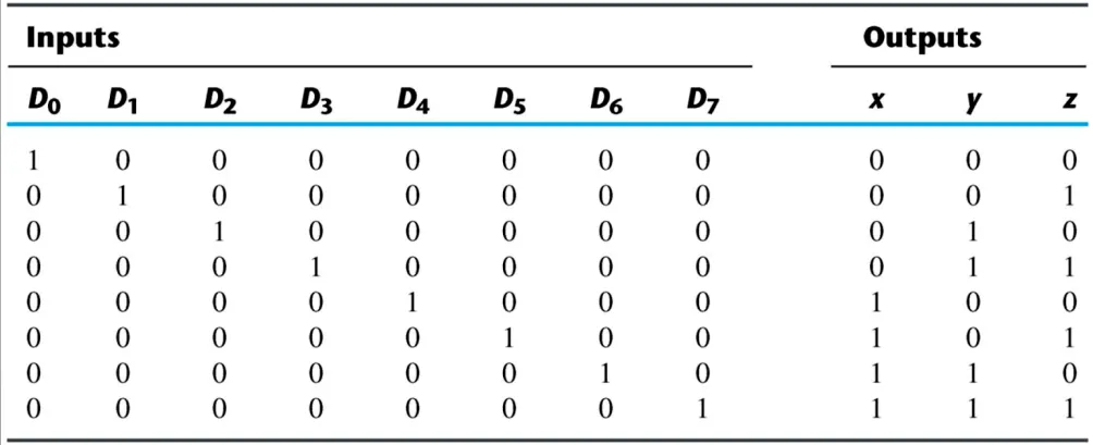 By observing the truth, we can get the Boolean function:
Priority Encoder#
- Allows multiple input lines to be asserted
- Higher-numbered input line has higher priority
- A priority encoder examines the input bits of an n-bit word and produces an output that indicates the position of the highest priority logic 1 bit.
4-to-2 priority encoder#
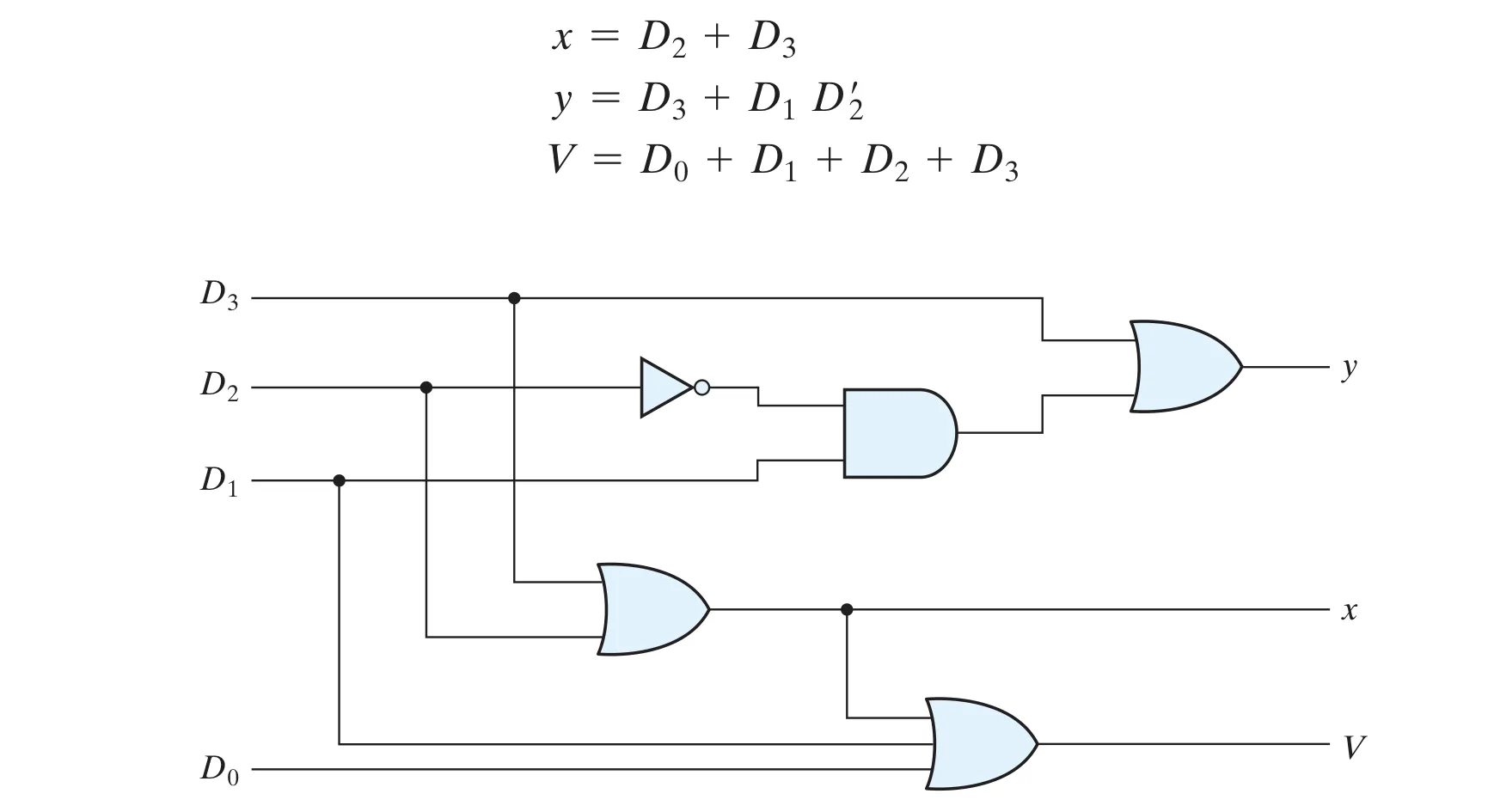
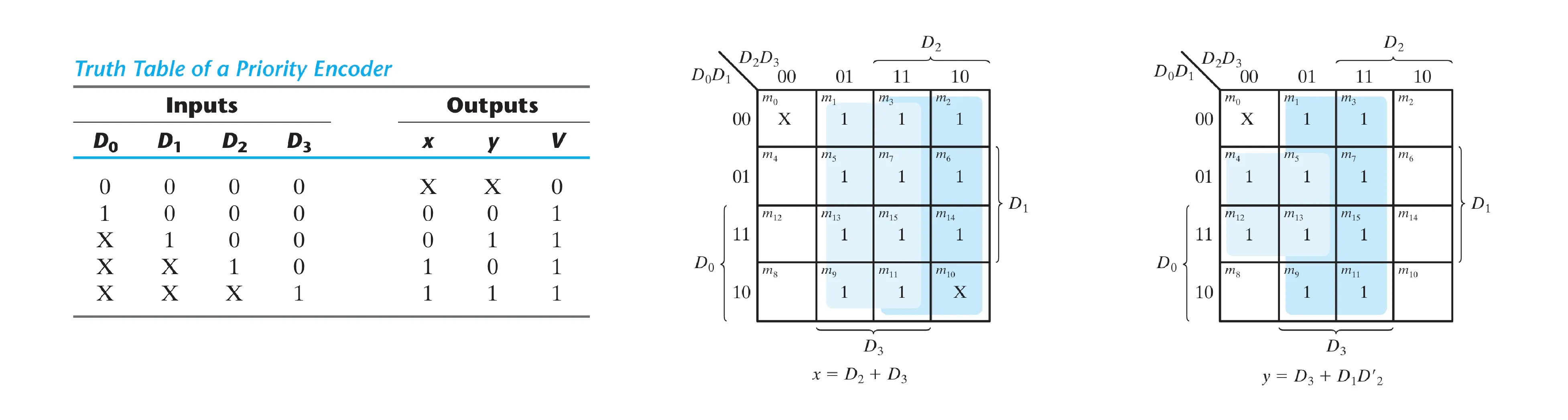 By Kmap, we can get the logic expression and draw the circuit:
Multiplexer (select one of N)#
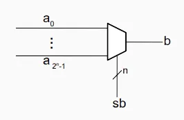
- A data selector
- data input lines, selection lines and one output line
- if
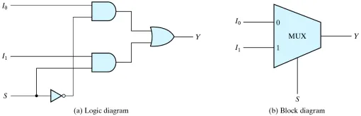
2-to-1 multiplexer#
We can easily draw the circuit:
4-to-1 multiplexer#
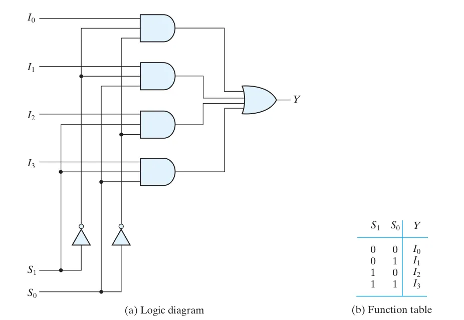 We can write this multiplexer with verilog:
module Mux4to1(a3, a2, a1, a0, sb, b);
    input a0, a1, a2, a3; // inputs
    input [1:0] sb; // binary select
    output b;
    reg b;
    always @(*) begin
        case(sb)
            2’b00: b = a0;
            2’b01: b = a1;
            2’b10: b = a2;
            2’b11: b = a3;
            default: b = x;
        endcase
    end
endmoduleMux tree#
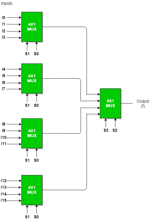
Reuse the multiplexer to construct a mux tree:
Utility#
Info:
Any function of variables can be implemented with a single MUX with selection inputs.
Example 1#
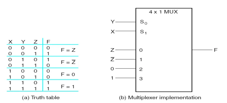
Implement the following function with MUX:
Suppose we use X and Y as the selection inputs and , respectively, then:
Example 2#
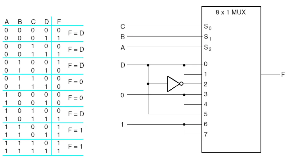
Implement the following function with MUX:
Using , , as , , respectively.
Tri-state Buffer#
- A type of buffer
- Output state : , , or (high-impedance).

Mux implemented by Tri-state Buffer#
| 2x1 MUX | 4x1 MUX | |
|---|---|---|
| Implementation | 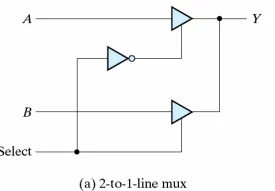 | 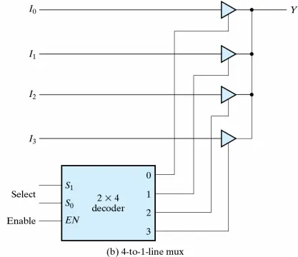 |